Electrical Interactive
What Is a Ufer Ground? NEC Requirements, Inspection and Testing
What a Ufer ground is, the NEC 250.52 requirements it must meet, and how our engineers inspect and test one in the field, with real resistance readings.

Contents
- What Is a Ufer Ground?
- Why Was Ufer Grounding Invented?
- What Are the Benefits of Ufer Grounding?
- Ufer Ground Requirements in NEC 250.52(A)(3)
- Ufer Ground Installation Happens Before the Pour
- Ufer Inspections
- How to Supplement a Ufer Ground That Doesn’t Meet NEC 250.52
- Ufer Ground FAQs
- Hiring Dreiym Engineering for a Ufer Inspection
A Ufer ground is a grounding electrode made of the reinforcing steel or bare copper wire inside a building’s concrete footing. Concrete holds moisture and sits in direct contact with the earth, so a Ufer ground usually makes a lower-resistance connection than a driven ground rod. Where a new building has a footing that qualifies, the NEC requires it to be bonded into the grounding electrode system. Below we explain where the name comes from, what NEC 250.52 requires, how the electrode goes in before the pour, and how our engineers inspect and test one in the field.
What Is a Ufer Ground?
A Ufer ground is a grounding electrode made of steel rebar or bare copper wire encased in the concrete footing or foundation of a building. The National Electrical Code (NEC) calls it a concrete-encased electrode. Concrete holds moisture and is in direct contact with the earth, so a Ufer ground usually makes a lower-resistance connection to earth than a single driven ground rod, especially in dry soil.
The name comes from Herbert G. Ufer, the engineer who developed the method during World War II. The Code only uses the formal name. In the trade you’ll also hear Ufer grounding called concrete-encased grounding or foundation grounding.
Why Was Ufer Grounding Invented?
Ufer grounding started as the answer to a US Army problem in the 1940s. The Army needed to protect its ammunition depots from lightning, but the desert soil where the depots were built was too dry and too resistive to make a good ground. Ufer found that the concrete the depots were made of had low resistance and could serve as an effective ground electrode. He worked out a way to connect the metal parts of the electrical system to the concrete foundations, which gave the depots a large, stable grounding network.
The method worked, and it was cheap and simple to put in. Grounding a depot the Ufer way was estimated at about $60, compared with $5000 for a conventional rod and grid system. Ufer grounding also needed less maintenance and less ground testing, because the concrete protected the electrode from corrosion and physical damage.
The US Army and Navy adopted Ufer grounding, and the NEC followed. Its 1968 edition was the first to recognize concrete-encased electrodes, and the 1975 edition added the steel rebar version. Since 2005, the Code has required a concrete-encased electrode to be bonded into the grounding electrode system wherever one is present at new construction. Over the decades, Ufer grounding has proven to be a reliable, safe way to protect electrical systems and the people who use them from electric shocks, fires, and surges.
What Are the Benefits of Ufer Grounding?
Compared with other electrodes, such as rods or plates, Ufer grounding has several advantages:
- It costs less and is easier to install, since there’s no hole to dig or drill.
- Corrosion, moisture, temperature, and soil conditions affect it less, so it’s more reliable and lasts longer.
- Its resistance is lower and it can carry more fault current, so the electrical system performs better and is safer.
- Lightning damage is less likely with Ufer grounding, because the discharge gets a low-impedance path to earth.
These advantages matter most in dry, rocky, or sandy soil, where driven rods struggle, and they explain why Ufer grounding is so common. It’s used in homes and in commercial and industrial buildings, and in telecommunication, power, and transportation systems too.
A Ufer ground can still be damaged, though. High lightning or fault current can flash the moisture trapped in the concrete to steam and spall it, so after a known high-current event, have the encasement and its connections inspected.
Even a low-resistance electrode can’t stand in for the neutral. If the service neutral fails, part of the current the neutral would normally carry goes back through the grounding electrode and the soil instead. The lower the electrode’s resistance, the more of that current it carries and the less the voltage swings above and below 120 V. But that current still lifts the grounded metal in the house above the utility’s neutral. Our article on what a lost neutral does to a home explains the voltages and the shock hazard this creates.
Ufer Ground Requirements in NEC 250.52(A)(3)
Under NEC 250.52(A)(3), a concrete-encased electrode can be used as a grounding electrode for any electrical system, as long as it meets these requirements:
| NEC 250.52(A)(3) requirement | Specification |
|---|---|
| Minimum length | 6.0 m (20 ft) of qualifying conductor encased in the concrete |
| Conductor options | Electrically conductive steel reinforcing bars or rods at least 13 mm (1/2 in.) in diameter, or bare copper conductor not smaller than 4 AWG |
| Concrete encasement | At least 50 mm (2 in.) of concrete around the conductor |
| Location | Horizontally near the bottom, or vertically, within a concrete foundation or footing in direct contact with the earth |
| Connection | Bonded to the grounding electrode conductor by an approved device or method, such as an exothermic weld, a listed lug, or a listed pressure connector |
Two allowances in the Code are easy to miss. The rebar doesn’t have to be one continuous 20 ft bar. Several bars tied together with the usual steel tie wires can make up the length. And if a building has more than one concrete-encased electrode, only one of them has to be bonded into the grounding electrode system.
The footing also has to be in direct contact with the earth. Recent NEC editions include an informational note saying that concrete separated from the soil by insulation, vapor barriers, or films isn’t considered to be in direct contact with the earth. In newer energy-efficient buildings, a polyethylene vapor barrier under the footing is one of the most common reasons a planned Ufer ground fails inspection, so coordinate with the concrete contractor before the pour.
NEC 250.50 sets out when a Ufer ground is required. If a concrete-encased electrode exists at a building or structure, it must be used, bonded together with all the other electrodes present. The International Building Code doesn’t set grounding electrode requirements of its own. IBC Chapter 27 refers electrical design and installation to NFPA 70.
If the concrete-encased electrode doesn’t meet these requirements, it still has to be bonded to the grounding system, and you’ll need to install another grounding electrode that does meet them, such as a conventional ground rod.
The NEC is revised every three years. The current edition is the 2026 edition, which NFPA issued in 2025. States and cities adopt new editions on their own schedules, so your jurisdiction may still be enforcing the 2023 or 2020 edition, or an older one. The core concrete-encased electrode requirements above haven’t changed much in recent editions, but always confirm the adopted code and any local amendments with your authority having jurisdiction (AHJ).
Related service
Ground Testing and Commissioning
Fall of potential, clamp-on, soil resistivity, bonding
Ufer Ground Installation Happens Before the Pour
The electrode goes in while the foundation is being built. Once the concrete is placed, nobody can see or move it anymore, and checking it gets expensive. Most of the job is coordination between the electrician, the concrete contractor, and the inspector.
Usually the electrode is steel that’s going into the footing anyway: at least 20 ft of 1/2 in or larger rebar. The other option is 20 ft of bare copper conductor, 4 AWG or larger. Either one sits low in the footing, with at least 2 in of concrete around it, and the footing has to be in direct contact with the earth.
Plan ahead for an accessible place to connect the grounding electrode conductor. That’s typically a rebar stub or a tail of the copper conductor brought out of the concrete, ready to be bonded with an approved connector, a listed lug, or an exothermic weld. Also confirm with the concrete contractor that no vapor barrier, insulation, or film will separate the footing from the soil. As noted above, concrete isolated from the earth isn’t considered to be in direct contact with it, and an isolated footing can’t serve as the electrode.
Then get the inspection on the calendar before the pour. A qualified electrical engineer or inspector can check the electrode while it’s still visible and can be corrected. After the pour, proving compliance depends on documentation, which we cover in the next section.
Ufer Inspections
Before the concrete is poured, a qualified electrical engineer or inspector has to inspect the Ufer (the concrete-encased electrode) and verify that it meets the requirements of the NEC. Never use the electrician who installed the Ufer as the inspector. Many authorities will reject that inspection.
If the concrete is already poured and the Ufer can’t be reached for inspection, the installer has to provide documentation proving the Ufer was installed according to the NEC. That can include photos (which have to meet some strict requirements), drawings, invoices, or certificates from the manufacturer or supplier of the conductor or the concrete. Normally the documentation needs to be good enough to hold up in court under extreme scrutiny. Just imagine someone getting shocked or electrocuted at the structure. That’s when the quality of this documentation will matter. Most electricians and builders can’t produce evidence-quality photo documentation, and hiring a forensic engineer just to photograph a slab is rarely worth the cost.
If there’s no documentation, or it isn’t good enough, the installer and inspector have to assume the Ufer doesn’t meet the NEC requirements and install another grounding electrode that does, such as a conventional ground rod. Usually the most cost-effective fix is simply to install two supplemental ground rods. For most residential structures, two rods meet NEC 250.52, and they also satisfy the rule for adding a second rod when the first one doesn’t meet the 25-ohm requirement to remote earth.
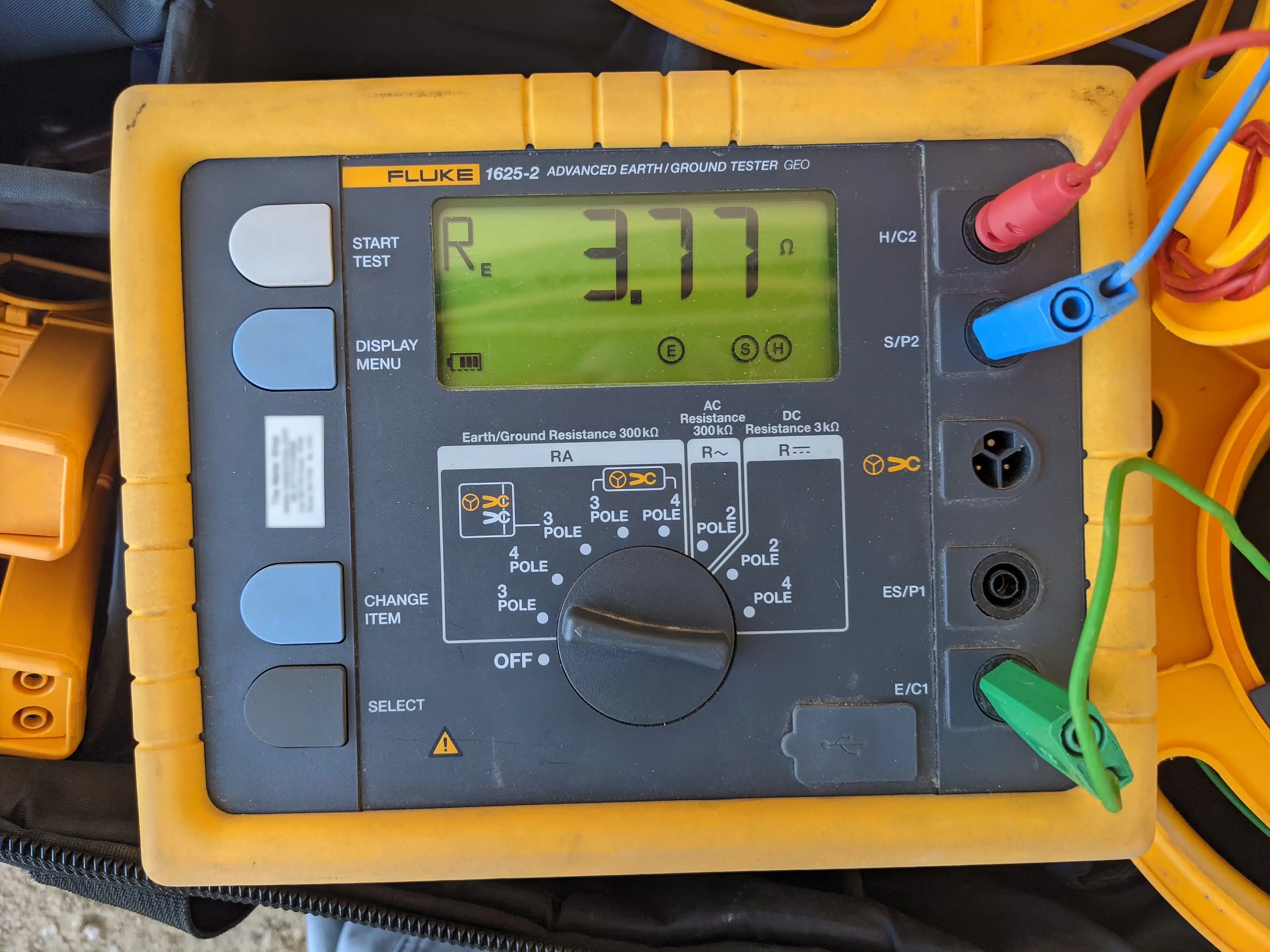
Fall of Potential Test on a Concrete Slab’s Ufer Connection
This test measures how good the electrical contact is between the electrical grounding system, through the concrete slab, and out to remote earth using the fall-of-potential method. Here, the test shows 3.77 ohms to remote earth.
A Ufer inspection should also confirm that the slab is continuous and electrically bonded, meaning there are no breaks or gaps in the concrete that would interrupt the flow of electricity through the Ufer. A discontinuous slab makes the Ufer less effective as a grounding electrode and raises the risk of step potentials inside the home. A step potential is the voltage difference between two points on the ground, and adults, children, or animals walking there can get electric shocks from it.

Slab Ufer Continuity Test
This test measures the strength of a signal walking over a large commercial slab. Here, the depth of a metallic structure is measured inside the slab at a specific location.
To check the slab’s continuity, we can run a toning test with a tone generator and a probe. The generator sends a signal through the Ufer, and the probe picks it up at the far end and across the slab. A clear, steady signal means the slab is continuous and well bonded. If the signal is weak or comes and goes, there are breaks or gaps in the slab that need to be repaired or bridged with copper wire. We can also find where the breaks or gaps are and recommend how to fix them.
How to Supplement a Ufer Ground That Doesn’t Meet NEC 250.52
Without the documentation or inspections to prove the Ufer meets the NEC requirements, you must install another type of grounding electrode that does. A ground rod is one of the most common and economical options. It’s a metal rod driven at least 8 feet into the earth. The rod has to be stainless steel or copper- or zinc-coated steel, and at least 5/8 inch in diameter unless it’s a listed rod electrode. It must be connected to the grounding electrode conductor with an approved clamp or connector, and that connection has to be accessible for inspection.
Under the NEC, a single ground rod is acceptable as a grounding electrode if its resistance to remote earth is 25 ohms or less. That resistance can vary with soil conditions and moisture, so we recommend measuring it with a ground resistance tester. The tester applies a known voltage and current to the rod and measures the voltage drop that results.
If the rod measures more than 25 ohms, you must install a second ground rod at least 6 feet from the first and connect the two in parallel with the grounding electrode conductor. The NEC doesn’t require you to measure the second rod, as long as it’s installed to the code’s specifications. It’s still good practice to check that the two rods together measure lower than the single rod did.
Dreiym Engineering can handle the testing of ground rods for your project. We have the equipment and the expertise to take accurate ground resistance measurements. We can also tell you where the rods should go and how far apart they should be, and make sure they’re properly connected to the grounding system. Afterward we can give you a report documenting our test results and whether your ground rods comply with the NEC.
Ufer Ground FAQs
Is a Ufer ground better than a ground rod?
In most soils it is. A code-compliant concrete-encased electrode has far more surface area in contact with the earth than an 8 ft rod, and concrete holds moisture, so a Ufer usually measures lower resistance to remote earth. The NEC accepts both. Where a footing with qualifying rebar is present at new construction, though, it must be used as part of the grounding electrode system.
How many ohms should a Ufer ground measure?
The NEC doesn’t set a resistance number for concrete-encased electrodes. The 25 ohm figure people often quote comes from NEC 250.53(A)(2), and it applies to rod, pipe, and plate electrodes. A single ground rod that measures more than 25 ohms to remote earth has to be supplemented with a second electrode. In our field testing, healthy Ufer connections commonly measure well below that. The slab test pictured earlier in this article read 3.77 ohms.
How do you test a Ufer ground?
The standard method is the fall-of-potential test described in IEEE 81. Temporary probes are driven into the earth at set distances, and the test measures the resistance between the grounding system and remote earth. A clamp-on tester gives a quick check, but it reads the whole parallel grounding path and can’t isolate the Ufer. A toning or continuity test shows whether the slab steel is electrically continuous.
Does every house have a Ufer ground?
Most newer homes on poured footings have one, because the NEC has required concrete-encased electrodes to be used where available since 1978, and wherever present since 2005. Older homes usually rely on ground rods or a metal water pipe instead. Even a new house can end up without a usable Ufer ground. If the footing was poured over a vapor barrier, or the connection stub was never brought out of the concrete, it can’t serve as one.
Can you add a Ufer ground to an existing building?
A Ufer ground has to be encased in footing or foundation concrete that’s in direct contact with the earth, so adding one to an existing building would mean breaking into the foundation or replacing it. The NEC recognizes the problem. Since 2005, 250.50 has included an exception for existing buildings where the reinforcing bars can’t be reached without disturbing the concrete. Existing buildings rely on driven ground rods, pipe or plate electrodes, a ground ring, or a qualifying metal underground water pipe instead (and the Code requires a water pipe electrode to be supplemented by an additional electrode). Realistically, the only way to get a new Ufer ground is to bond qualifying rebar the next time foundation concrete is poured, for an addition, a foundation replacement, or a new detached structure.
Hiring Dreiym Engineering for a Ufer Inspection
A Ufer that doesn’t meet the NEC can compromise the grounding of your electrical system, and with it the system’s safety and reliability. That can mean electrical hazards, equipment damage, or power outages. An inspection tells you whether yours meets the NEC.
We can inspect a Ufer before or after the concrete is poured. Our electrical engineers know the NEC requirements and the installation details that cause most Ufer grounds to fail inspection. We check your Ufer against the requirements for size, length, location, encasement and connection to the grounding electrode conductor, and we document our findings and recommendations.
When the concrete is already in and the Ufer is out of reach, we can help you obtain or prepare the documentation to prove it was installed according to the NEC. We’ll review your photos, drawings, invoices, or certificates and check them against the strict criteria for acceptance. We can also test your grounding system for resistance and continuity and give you a report of the results.
We work with contractors, homeowners, architects and design engineers to get electrical systems grounded properly and in line with the NEC. Tell us your pour date and contact us for a free quote.
Always consult your licensed electrical installer or design professional to make sure all requirements of the NEC and other applicable codes are met.