Electrical Interactive
Fall of Potential vs. Point-to-Point: What Each Ground Test Proves
How far to place the current probe in a fall of potential test, the 62% rule, 12 common mistakes, and why ground resistance can't prove bonding.
Contents
- Fall of Potential vs. Point-to-Point at a Glance
- What a Fall-of-Potential Test Measures
- What a Point-to-Point Test Measures
- When to Use a Fall-of-Potential Test
- The Limits of Fall-of-Potential Testing
- Bad Engineering: Using Fall of Potential to Check Bonding
- When to Use a Point-to-Point Ground Bonding Test
- The Limits of Point-to-Point Testing
- A Related Test: Pipeline Bonding and Continuity
- Which Test to Use: Common Situations
- Why a Complete Grounding Evaluation Uses Both
- Frequently Asked Questions
- How Dreiym Engineering Can Help
A fall-of-potential test measures how well a grounding electrode or grid connects to the earth: its resistance to remote earth. A point-to-point test measures the metal path between two parts of the grounding and bonding system, such as the main ground bus and an equipment frame. They answer different questions. However good its number, a fall-of-potential test cannot prove that equipment is effectively bonded.
Below we compare fall of potential vs. point-to-point testing: when to use each, where each falls short, and which fits common situations.
Fall of Potential vs. Point-to-Point at a Glance
| Fall of potential | Point-to-point | |
|---|---|---|
| Measures | Resistance from an electrode or grid to remote earth | Resistance of the metal path between two points |
| Typical values | Ohms, or under 1 ohm for large grids | Milliohms to a fraction of an ohm |
| Answers | Does the electrode meet 25 ohms, or its specified value? | Is this equipment bonded to the grounding system? |
| Can’t answer | Is the equipment bonded? Will a ground fault clear? | What is the resistance to earth? |
What a Fall-of-Potential Test Measures
The fall-of-potential (three-point) test is the standard grounding electrode resistance test described in IEEE Std 81. The tester passes a current between the electrode under test and a current probe driven into the soil some distance away, and measures the voltage between the electrode and a potential probe between them. Voltage divided by current is the resistance to earth.
For a small electrode such as a single rod, in uniform soil, with the current probe far enough away, a potential probe at 62 percent of the distance to the current probe reads the true resistance. Layered soil or a current probe set too close upsets that, so the reading is checked with the potential probe moved 10 percent of the spacing either way. For a ground ring or grid, plot readings across the whole traverse. The flat part of the curve, the plateau, is the electrode’s resistance, as Figure 1 shows. No plateau means the current probe has to go farther out.

Many testers also offer a four-pole connection, which adds a sense lead at the electrode so the test lead’s resistance drops out.
How Far Away to Put the Current Probe
Every electrode is surrounded by a zone of soil, its resistance area, that accounts for most of its resistance to earth, and the current probe has one too. The potential probe has to sit in undisturbed soil between the two zones. If the current probe is too close, the zones overlap, the curve never flattens and no single reading is right, as Figure 2 shows.
IEEE Std 81 derives the 62 percent rule for an electrode in uniform soil with the current probe far enough away that the two resistance areas don’t overlap, and calls for checking the curve rather than trusting a single reading. The distance that takes scales with the size of the electrode, not the size of the site. Our rules of thumb:
- A single rod: place the current probe 5 to 10 times the rod’s driven depth away.
- A ground ring, a grid or a slab (Ufer) electrode: place it 10 times the diagonal across the whole system away.
Measure from the center of the electrode system, and start with the potential probe at 62 percent of that distance. Figure 3 works through the examples in this table:
| Electrode | Size used | Current probe | Potential probe at 62% |
|---|---|---|---|
| Single 8 ft rod | 8 ft depth | 40 to 80 ft (5 to 10 times) | 25 to 50 ft |
| Single 10 ft rod | 10 ft depth | 50 to 100 ft (5 to 10 times) | 31 to 62 ft |
| 40 ft by 60 ft ground ring | About 72 ft diagonal | About 720 ft (10 times) | About 446 ft |
| 100 ft by 150 ft slab or Ufer | About 180 ft diagonal | About 1,800 ft (10 times) | About 1,116 ft |
A rod can be tested on most sites. A ring needs a long, clear run, and a building slab can need a third of a mile of open ground. Where the room isn’t there, the selective and clamp-on methods described below are the usual alternatives, and IEEE Std 81 describes ways to analyze the curve from a large system when a full plateau can’t be reached. Whatever the distance, plot the curve and confirm it flattens before trusting the number.


What a Point-to-Point Test Measures
A point-to-point ground test, also called a two-point continuity test or bonding resistance test, measures the metal path between two points in the grounding and bonding system, such as from the main ground bus to an equipment frame, building steel or a transformer’s neutral-to-ground bond. The soil isn’t part of the circuit.
It’s a simple two-lead test. An earth ground tester such as a Fluke 1625-2 is set to its two-pole AC resistance mode, the resistance of the test leads is compensated (nulled) first, and one lead is clamped to each point. The tester passes an AC test current through the metal path between the clamps and reads its resistance, as Figure 4 shows. A sound bond reads a small fraction of an ohm.

When to Use a Fall-of-Potential Test
Use fall of potential when the question is how well the electrodes connect to earth:
- Acceptance testing of a new electrode or grid against its design value.
- Showing that a single electrode meets 25 ohms. NEC 250.53(A)(2) requires a single rod, pipe or plate electrode to be supplemented by a second electrode unless it has a resistance to earth of 25 ohms or less. Only a test can use that exception. With the second electrode installed, the NEC requires no test and sets no value. The NEC edition your jurisdiction has adopted governs.
- Meeting a specified resistance, often well below 25 ohms in utility, telecom and data center specifications.
- Trending an electrode tested the same way over the years.
The Limits of Fall-of-Potential Testing
It Cannot Prove Effective Bonding
A fall-of-potential test looks outward from the electrode into the soil. It says nothing about whether equipment grounding conductors are continuous, bonding jumpers are tight, or a transformer, motor or building steel is tied in at all. A grid can measure 1 ohm beneath a switchboard whose ground bus was never connected to it, as Figure 5(a) shows. Done properly, the test isolates the electrode, so by design it leaves out the connections bonding depends on.
It Doesn’t Show That a Ground Fault Will Clear
Ground-fault current returns to its source over the equipment grounding conductors and bonding jumpers, not through the soil. NEC 250.4(A)(5) requires an effective ground-fault current path and states that the earth is not one. A 120-volt fault through a 25-ohm electrode can drive at most about 5 amperes, far too little to trip a 20-ampere breaker, so the faulted equipment stays energized.
Parallel Paths Have to Be Removed
At a typical service, the electrode is bonded to the service neutral, which ties it to the utility’s grounded neutral and other electrodes, so testing it in place measures that whole network and reads low. The electrode has to be isolated, or measured with the selective method, which puts a current clamp around the electrode so only the test current through it counts. Isolating it means opening the grounding electrode conductor, which at an energized service is hazardous: current may be flowing on it, and the system loses its electrode while it’s open. Follow safe work practices such as NFPA 70E, or de-energize.
The clamp-on (stakeless) method needs no probes, but it measures a loop: the electrode in series with all the other grounds in parallel. It works only where there are many parallel return paths, never on a single isolated electrode.
It Needs Room and Clean Soil
The probes need a straight run of open ground, and a large grid can need the current probe hundreds or even thousands of feet out: impractical on most plant sites, impossible on a paved urban lot. Buried pipes, fences and rebar distort the curve, and stray currents add noise. See our post on testing grounding systems at large sites.
It Isn’t a Step and Touch Voltage Study
A low resistance to earth doesn’t make a substation safe to stand in during a fault. Step and touch voltages are evaluated through an IEEE Std 80 analysis built on soil resistivity data, the fault current and the grid layout. The measured resistance is only one input.
Related service
Ground Testing and Commissioning
Fall of potential, clamp-on, soil resistivity, bonding
Bad Engineering: Using Fall of Potential to Check Bonding
A fall-of-potential test on a building, a tank, a tower or a skid is sometimes offered as proof that the structure and its equipment are bonded. It isn’t, and the reports built on that idea tend to repeat the same mistakes:
- Calling a low earth resistance proof of bonding. “The structure measured 2 ohms, so it’s bonded” confuses two different paths. The test measured the soil around an electrode, not the conductors and connections between the structure and its equipment.
- Testing the electrode without isolating it. With the grounding electrode conductor still connected, the tester measures the electrode in parallel with the utility’s multigrounded neutral and every other bonded electrode. The reading comes out low almost every time, and it gets reported as the electrode’s resistance.
- Clamping the E lead to whatever steel is handy. A column, a handrail or a fence post connects to an unknown mix of steel, piping and neutrals. The number describes that mix, not the bond to the switchboard 200 feet away.
- Using one fixed probe spacing for everything. A current probe at 100 feet may be fine for a single rod. On a building or a plant grid it sits inside the electrode’s own resistance area, the curve never flattens, and the 62 percent reading is reported anyway.
- Taking a single reading. No curve, no check with the potential probe moved 10 percent either way, and no way to tell whether the number means anything.
- Running probes and leads along buried metal. Probes driven near buried pipe, fences or rebar, or test leads laid alongside the structure itself, distort the reading in ways a single number won’t show.
- Treating 25 ohms as a pass mark for bonding. The NEC’s 25 ohms decides whether a single rod, pipe or plate electrode needs a supplemental electrode. It has nothing to do with bonding, where a sound connection reads a small fraction of an ohm.
- Assuming a low earth resistance means faults will clear. Fault current returns on the equipment grounding conductors and bonding jumpers. The earth is not an effective ground-fault current path, however low its resistance.
- Letting one test point stand in for the whole structure. A reading at one location says nothing about the motor, the transformer, the tank or the frame that was never connected.
- Misreading a clamp-on test. A stakeless clamp around a conductor that loops back through bonded steel measures the metal loop, which reads close to zero and gets written up as an excellent ground.
- Lifting the grounding electrode conductor on an energized service to isolate the electrode, with no safe work plan, while current may be flowing on it.
- Leaving out how the test was done. Without probe positions, lead routing, soil conditions and instrument settings, the result can’t be repeated, trended or defended, and it often ends up under a PE stamp that says the grounding and bonding were “verified”.
The fix is simple: use fall of potential for the electrode’s connection to earth, and point-to-point tests for every bond that matters, each documented so someone else can repeat it.
When to Use a Point-to-Point Ground Bonding Test
Use point-to-point testing whenever the question is whether metal is connected to the grounding system: after construction, modifications or added equipment; after ground faults, storms and lightning, which can burn open or loosen connections; and in acceptance and maintenance testing to ANSI/NETA ATS and MTS.
The NETA grounding-system item calls for point-to-point tests between the main grounding system and major electrical equipment frames, the system neutral and derived neutral points, and for investigating values above 0.5 ohm. That figure is a trigger for investigation, not a pass mark. The same item also calls for a fall-of-potential or other IEEE Std 81 test of the main grounding electrode, so the standard asks for both.
The Limits of Point-to-Point Testing
- It says nothing about resistance to earth. A perfectly bonded building can sit on a corroded rod that reads hundreds of ohms.
- Parallel paths can hide an open bond. In a meshed system, a cut bonding jumper can still read low through conduit, building steel or another conductor, as Figure 5(b) shows. Measure across the specific jumper you need to prove, and compare similar equipment for outliers.
- A low test current can pass a bad joint that later overheats or fails under fault current. IEEE Std 81 describes high-current integrity testing, used mainly on substation grids, to expose such joints.
- It doesn’t verify conductor size. Fifty feet of 14 AWG copper, far too small for a large feeder, reads roughly 0.15 ohm, well under 0.5 ohm. Whether a conductor can carry the fault current is checked against the drawings and the NEC sizing rules.
- It isn’t the IEEE 81 two-point method. That method estimates an electrode’s resistance to earth by measuring it in series with a known low-resistance ground, such as a metallic water piping system. It’s a rough earth-resistance estimate, not a bonding test, and if the two grounds are bonded through metal, it reads the bond instead.

A Related Test: Pipeline Bonding and Continuity
Buried pipelines raise the same question, whether the metal is connected, for a different reason. A cathodic protection system only protects pipe it is electrically connected to, so bonds across mechanical couplings, and between structures meant to share one system, have to be continuous. A coupling or bond that has failed leaves the pipe beyond it without protection.
Pipe and bond resistances are far lower than a building’s bonding readings, so pipeline continuity is checked with a four-wire setup instead of a two-point test. A DC test current is passed through the pipe on two outer leads, and the voltage drop across the bond or coupling is measured on two inner leads, as Figure 6 shows. Because the voltage is measured separately from the current, the leads’ own resistance doesn’t affect the result. Readings are taken with the test current on and off, or with its polarity reversed, so the pipe’s own cathodic protection current and any stray current cancel out. Continuity checks are part of cathodic protection commissioning and of tracking down interference and shorted or failed bonds.

Which Test to Use: Common Situations
- A single ground rod, to avoid a supplemental electrode: fall of potential, with the rod isolated.
- A new substation, data center or telecom grid with a specified resistance: both: the grid against its specification, and the bond from it to every frame and neutral.
- A new transformer, generator or UPS: point-to-point to the new equipment and its neutral-to-ground bond.
- After a fault or lightning strike: point-to-point first, plus fall of potential if the electrode may be damaged.
- Routine maintenance: both, compared with earlier results.
- A paved site with no room for probes: selective or clamp-on testing, where parallel paths allow.
- A claim that turns on whether equipment was grounded: point-to-point, documented as found.
- Bonds and couplings on a cathodically protected pipeline: a four-wire continuity test.
Why a Complete Grounding Evaluation Uses Both
Grounding and bonding do different jobs. The earth connection limits voltage from lightning, surges and contact with higher-voltage lines and stabilizes the system voltage to earth. The bonding path carries fault current back to the source so breakers and fuses operate. Fall of potential checks the first job and point-to-point the second, so a complete evaluation uses both, plus a visual inspection. To design or improve a system, start with a Wenner four-pin soil resistivity survey: the design is built on it, and it explains later readings.
Frequently Asked Questions
Can a multimeter be used for a bonding test?
Only as a rough continuity check. A sound bond reads a small fraction of an ohm, which is near the limit of most multimeters’ resolution and easily thrown off by lead and contact resistance. Use an earth ground tester in its two-pole AC resistance mode, with the test-lead resistance compensated.
Does weather affect ground test results?
Resistance to earth changes with soil moisture and temperature, so a reading taken after heavy rain can flatter an electrode. Record the conditions with every fall-of-potential test. Point-to-point readings measure metal, so the soil barely affects them.
How often should grounding and bonding be tested?
At installation, then on your maintenance program’s interval, and after repairs, added equipment, faults or lightning. Our post on how often ground systems should be tested covers the factors.
How Dreiym Engineering Can Help
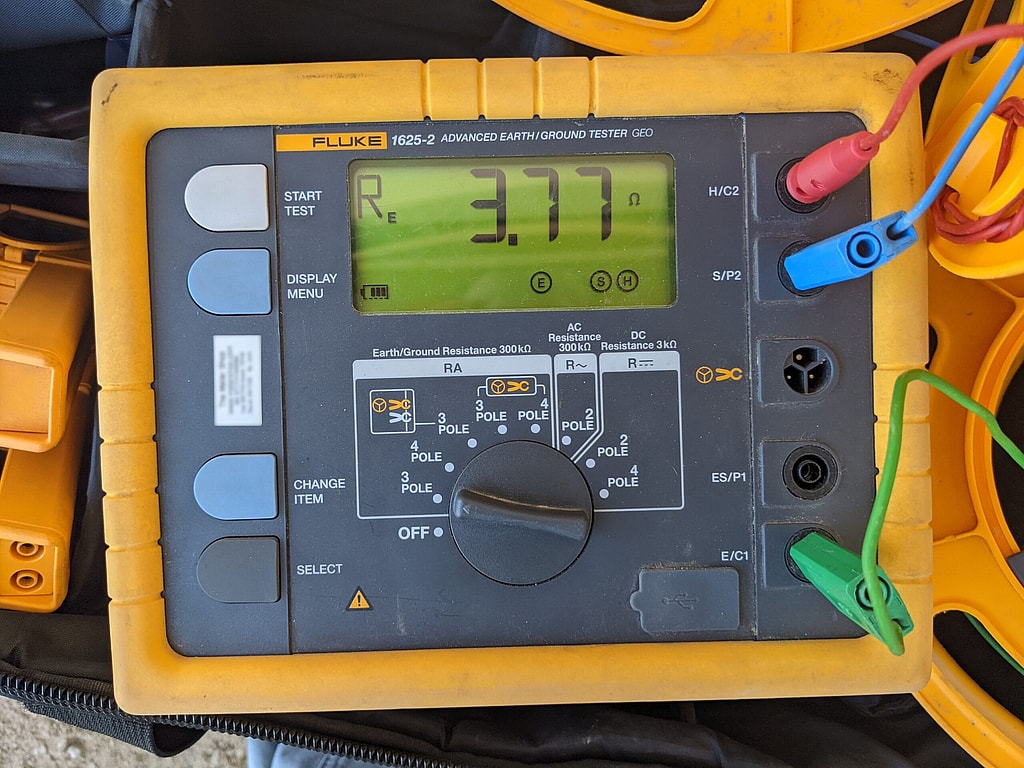
We perform both fall-of-potential and point-to-point testing with a Fluke 1625-2 earth ground tester as part of our grounding system tests, and we test to ANSI/NETA ATS or MTS when your project specifies it. When an owner, utility, telecom or data center specification sets a stricter target than the NEC’s 25 ohms, we test to it. Our electrical power engineers also perform short circuit analysis, which finds the fault current a bonding path must carry, and our forensic electrical engineers investigate failures where grounding may be to blame. On pipelines, our corrosion engineers check bonds and continuity as part of cathodic protection testing and commissioning. Reports are PE-stamped where required. Contact us for a free quote.