Consulting Areas
Cathodic Protection Interference Testing
We typically respond within one business day.
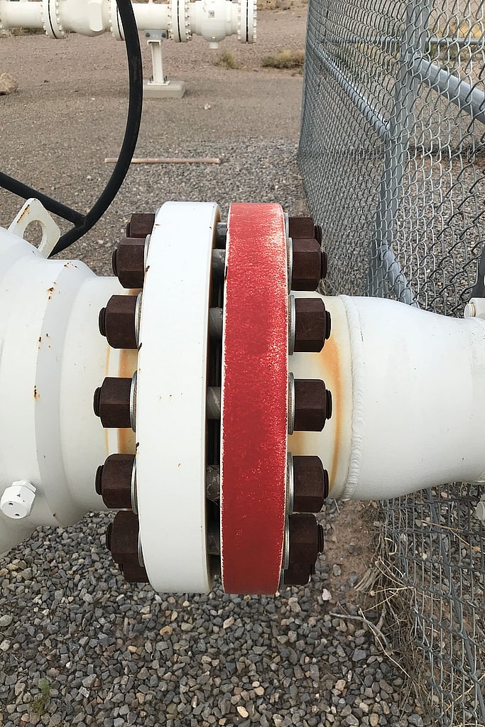
What Is Cathodic Protection Interference?
Cathodic protection interference happens when current from another structure’s CP system, a DC transit or mining operation, or a nearby high-voltage power line flows onto your pipeline or tank and leaves it somewhere else. Where that stray current leaves your structure, it removes metal, and it can corrode a well-protected pipe faster than having no CP at all. Interference testing finds where current is being picked up and discharged, measures how much, and shows how to fix it. Our article on what causes cathodic protection interference explains the mechanisms.
The figure below shows one of these sources, a DC rail line, on a simple model: move the train, change the rail insulation or add a drain bond to see where current leaves a nearby pipe.
- Traction substation: DC out to the overhead wire, back through the rails.
- The train draws current from the wire and returns it through the rails.
- Some of the return current leaks from the rails into the soil.
- The pipe collects part of it. Where current enters the pipe, the pipe is protected.
- Near the substation the current leaves the pipe for the rails. Where it leaves, the steel corrodes.
- Drain bond: a cable that brings the current back to the substation through metal.
Current leaves the pipe near the substation, and that is where the steel is lost: about 146 kg a year if this current flowed all year. Real trains come and go, so the yearly loss follows the average current.
Rail insulation
Interference most often shows up when:
- A new CP system, rectifier or pipeline is installed near existing structures
- Pipelines cross, or share a right-of-way with high-voltage power lines
- Potentials at a test station shift for no obvious reason, or rise and fall with a nearby rectifier
- Leaks appear at crossings or near foreign anode beds
Federal pipeline safety rules (49 CFR 192.473 and 195.577) require operators to minimize the harmful effects of interference currents. Contact us for a free quote. We typically respond within one business day.
For pipelines that share a corridor with high-voltage power lines, the page on AC interference and mitigation covers touch voltage, AC corrosion, modeling and mitigation design.
Related work: Oklahoma stray current investigation.
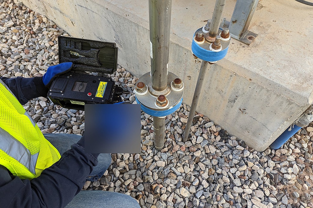
CP Surveys
Interference testing is cathodic protection testing aimed at one question: is someone else’s current affecting your structure, or is yours affecting theirs? Our field work is led by a licensed Professional Engineer, and our team includes a NACE CP Specialist (CP4) and a NACE CP Technologist. We record structure-to-soil potentials at test stations and crossings while the suspected source is switched on and off, so the effect of each rectifier or bond is measured directly rather than guessed.
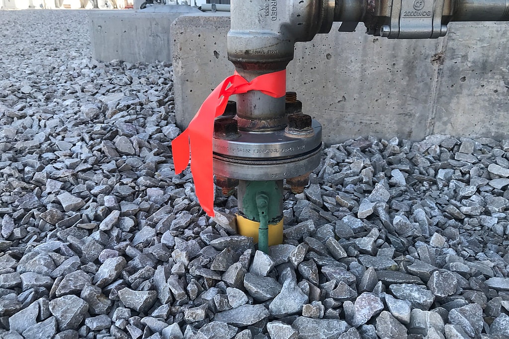
Insulating flange on a pipe riser
Before a new system goes in, we evaluate the site for foreign pipelines, rectifiers, anode beds and power lines that could interfere with it, and, with their owners’ cooperation, test nearby structures to see whether your system will affect them. Placing a groundbed correctly at the design stage costs far less than moving it later. If an existing system is already causing or suffering interference, we find the source and recommend the fix: a resistance bond, a rectifier adjustment, a relocated groundbed, added anodes or AC mitigation.
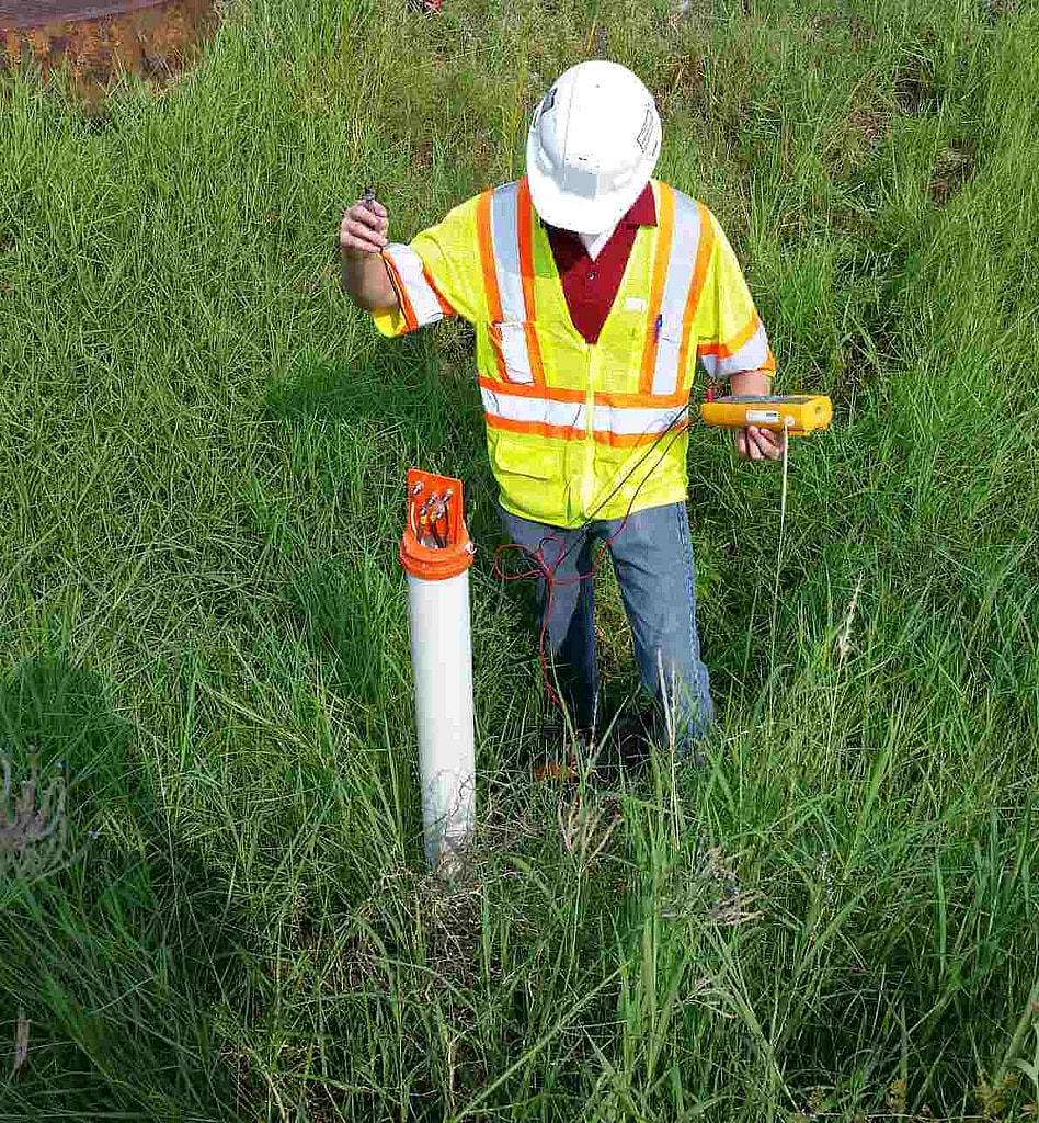
Cathodic Protection Startup
What we test:
- Test station potential surveys
- Close interval surveys
- Road and highway crossings
- Foreign pipeline crossings
- Interference bonds and bond stations
- Fence lines
- Fault protection and AC mitigation
- AC interference and induced voltage near power lines
- Automatically controlled rectifiers
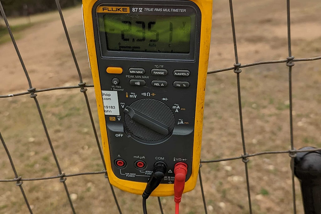
We perform interference testing across Texas and Colorado and in the surrounding states. Every project ends with a written report: the potentials we measured with each source on and off, where current is being picked up and discharged, and the mitigation we recommend, PE-stamped where required.
Contact us for a free quote on your project. We typically respond within one business day. Learn more about our Colorado services, and for work in shared corridors, see AC interference and mitigation in Colorado.
Frequently Asked Questions
What causes cathodic protection interference?
Current from a source other than your own CP system flowing through the soil and onto your structure: a foreign rectifier and anode bed, a DC traction or mining system, or voltage induced by a nearby AC power line. Corrosion happens where that current leaves your structure.
How is interference tested?
We measure structure-to-soil potentials at test stations, crossings and suspect locations while the suspected source is switched on and off with a synchronized interrupter. A change that follows the source’s cycle shows interference and how large it is.
How is interference fixed?
Common fixes are a resistance bond between the structures, adjusting or relocating a rectifier or anode bed, adding galvanic anodes where current discharges, coating the crossing, and grounding or gradient control for AC interference.
Do you need permission to test a foreign structure?
Yes. Testing on another owner’s pipeline is coordinated with that owner, and the most useful interference tests are run jointly so both sides can switch their rectifiers.
Related Reading
- What Causes Cathodic Protection Interference?
Learn what causes cathodic protection interference, from stray current and nearby CP systems to power lines, and how testing keeps pipelines protected.
- Why Cathodic Protection Systems Stop Working: 7 Problems Operators Should Know
Cathodic protection systems fail quietly. Here are 7 common causes, from rectifier faults to stray current, and the test readings that flag trouble early.
- How To Interpret Cathodic Potential Protection Survey Data
Learn how to interpret cathodic protection survey data (on, instant-off, and depolarized potentials) and what the -850 mV criterion means for your pipeline.
Related Services
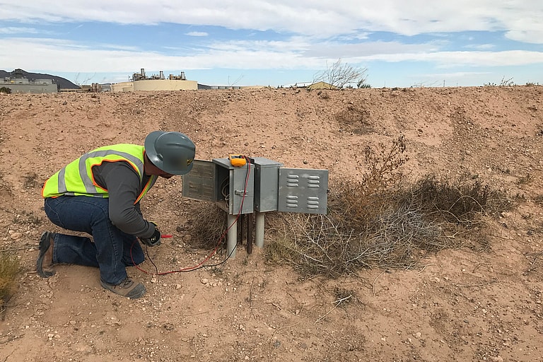
Potential Surveys
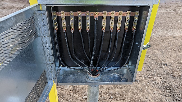
Corrosion Control Design
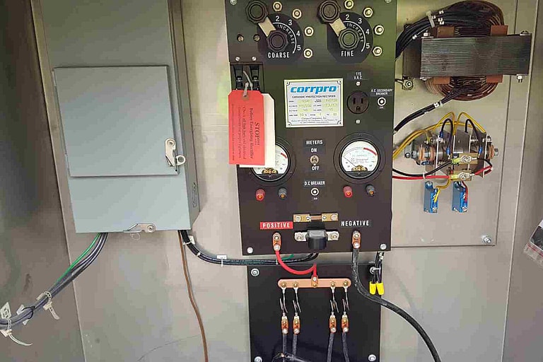
Start-up and Commissioning
Get your project started
We typically respond within one business day.