Consulting Areas
Protective Device Coordination Studies
We typically respond within one business day.
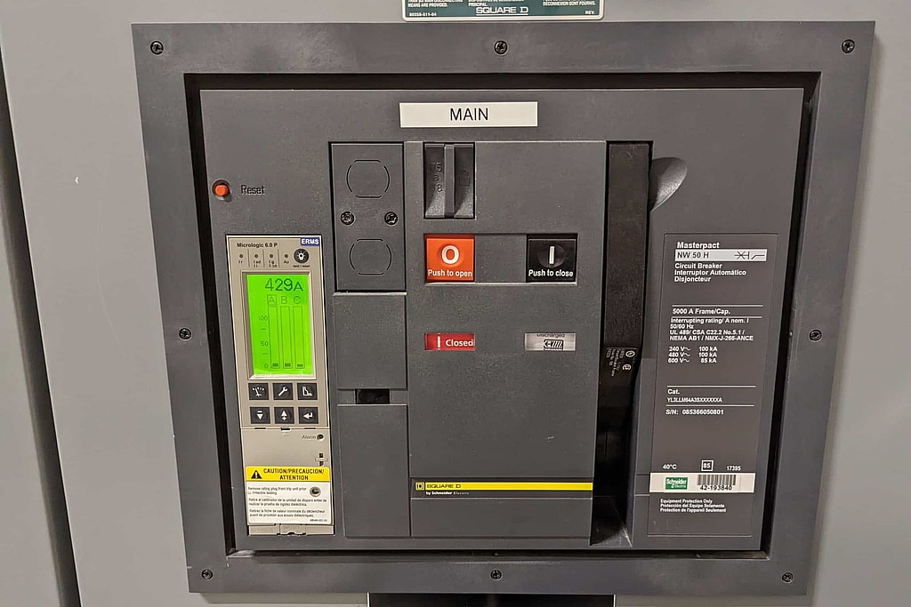
Selective coordination Illustrative
Selectivity on a time-current chart
A fault should open only the device nearest to it while every device upstream rides through. Set the main breaker’s trip unit, add a fuse and move the fault current to see where the curves stay apart and where they overlap. Generic curves for learning, not a coordination study.
On the chart, drag the round, diamond and square handles or the fault line; every setting also has a control beside the chart.
Selective at 10,000 A
The feeder breaker clears the fault by 0.025 s. The main breaker cannot trip before 0.26 s, a margin of 0.24 s.
| Device | At this fault | Earliest trip | Clears by |
|---|---|---|---|
| Main breaker, 1,600 A | Rides through | 0.26 s | 0.34 s |
| Feeder breaker, 400 A | Clears the fault | 0.01 s or less | 0.025 s |
| Fuse, 100 A |
Where coordination is lost
- Main and feeder breakers: selective over the whole range shown.
Hatching on the chart marks these currents. Near the bottom of the chart, 0.01 s or less, the curves alone cannot show which device opens first.
What Is a Protective Device Coordination Study?
A protective device coordination study, also called a protection coordination study or simply a coordination study, sets and checks the breakers, fuses, trip units and relays in your electrical system so the device closest to a fault opens first and everything upstream stays closed. We plot each device’s A log-log plot of how long a breaker, fuse or relay takes to operate at each level of current. Plotting the devices in series on one sheet shows whether the one nearest a fault will clear it first.See the glossary, compare the curves along every path from the utility service to the loads, and recommend settings that isolate a fault without shutting down more of the facility than necessary.
The same study confirms those settings still protect cables and transformers, and it supplies the clearing times an arc flash study depends on. Our coordination studies are led by licensed Professional Engineers, and when you call, you talk to an engineer. Ask for a free quote. We typically respond within one business day.
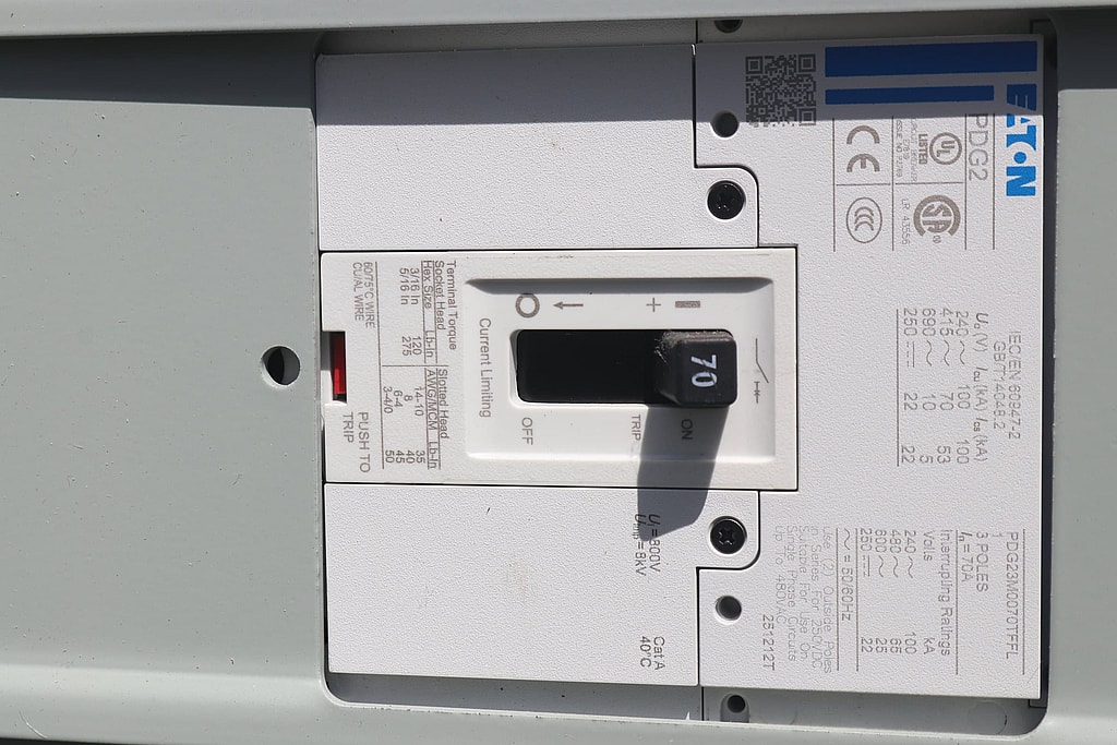
Molded case circuit breaker
What’s Included
- Field walkdown to record device types and present settings
- Time-current curves (TCCs) for every coordination path
- AC and DC, phase and ground overcurrent coordination
- Trip unit and medium-voltage relay settings
- ANSI or IEC basis, modeled in ETAP® or SKM
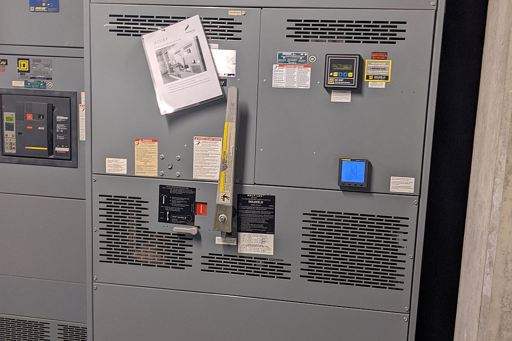
Main switchboard in an apartment building
Benefits
Correct coordination limits the impact an isolated failure can have on your system. Without it, a fault on one branch can trip a feeder or main breaker and cause a wider outage than it takes to clear the fault. When devices are properly coordinated, a single load failure won’t take out more of your facility than is needed to prevent loss or damage from fire.
The settings also have to protect cables and transformers, ride through motor starting and inrush, and keep arc flash The heat an arc flash could deliver to a worker’s face and chest at the working distance, in calories per square centimeter (cal/cm²). Arc-rated clothing and face protection must be rated at or above it.See the glossary in check.
Where the NEC Requires Selective Coordination
The NEC® requires Coordination that holds for every overcurrent up to the available fault current, so only the device protecting the faulted circuit opens. The NEC requires it for emergency, legally required standby and critical operations power systems and some elevator circuits.See the glossary for emergency (700.32), legally required standby (701.32) and critical operations power systems (708.54), some elevator feeders (620.62) and health care essential electrical systems (517.31(G)). We provide The organization, office or person who enforces a code and approves equipment and installations, such as a city or county building official, a fire marshal or a state agency.See the glossary-ready selective coordination documentation.
Deliverables, and What Affects Cost and Schedule
Every study comes with a written report, overseen by a licensed Professional Engineer and PE-stamped where required. It includes:
- TCC plots for each coordination path
- Recommended settings for each adjustable device, in a table electricians can work from
- A list of miscoordinated or misapplied devices, with recommendations
- An updated one-line diagram that matches what’s installed
- AHJ-ready selective coordination documentation where the NEC requires it
Pricing and our rate schedule are available on request. These are the main things that drive price and timeline:
- System size: the number of buses and adjustable devices to model and set.
- Drawings: an accurate one-line diagram saves field time. Missing or outdated drawings mean more walkdown work.
- Access: reading trip settings and nameplates can mean opening equipment, scheduled around operations.
- Utility data: the utility has to supply its The most current that could flow at a point in the system during a short circuit, set by the utility source, transformers, cables and running motors. Equipment there must be rated to interrupt or withstand it.See the glossary and The ratio of the system’s reactance (X) to its resistance (R) up to the fault. A higher ratio gives a larger, more offset current in the first cycles of a fault, which breakers and fuses must be rated for.See the glossary, and response times vary.
- Code scope: NEC selective coordination takes more analysis than a general coordination review.
- Bundling: doing the short circuit analysis, coordination and arc flash studies on one model avoids collecting the same data twice.
Who does the work
Brian J. Brackensick, M.S., P.E., leads our coordination studies. Ruben A. Rodriguez does the field data collection. Our engineers are licensed Professional Engineers with active and past licensure in multiple states. Dreiym Engineering was founded in 2014, and our team has over 30 years of combined experience. More about the team is on our staff page.
Since 2018 we’ve run a standing program of arc flash and protection coordination studies for industrial facilities around Greater Houston, and we restudy each plant when it adds load, replaces breakers or the utility changes its service. Read about the Houston program.
Dreiym serves Texas and the surrounding states and takes on studies nationwide. When you contact us, you go straight to an engineer instead of a phone tree. Contact us for a free quote and a scoped proposal. We typically respond within one business day.
Before the study
Build a data request for your study
Arc flash, short circuit and coordination studies start from the same system data. Tick what applies, then print the list for whoever gathers it. Anything you cannot find, we can collect on site.
Frequently asked questions
What is a coordination study?
A coordination study is an engineering analysis of the overcurrent protective devices in an electrical system, meaning the breakers, fuses and their trip settings. It compares the time-current characteristics of devices connected in series and recommends settings so that, for any overload or fault, the device nearest the problem operates first. “Coordination study,” “protection coordination study” and “protective device coordination study” all refer to the same work.
What is selective coordination?
Selective coordination is coordination that holds for every overcurrent up to the maximum available fault current, so only the device protecting the faulted circuit opens. The NEC requires it for emergency, legally required standby and critical operations power systems and for certain elevator feeders. Health care essential electrical systems must be coordinated for faults lasting longer than 0.1 second. Other systems are usually coordinated as far as is practical, balancing selectivity against equipment protection and arc flash.
Do I need a short circuit study before a coordination study?
Yes. Coordination has to be checked up to the fault current available at each device, so the short circuit analysis comes first. We normally do both on the same model.
Can coordinating my breakers make the arc flash hazard worse?
It can. Delaying an upstream device so a downstream device clears first also lengthens how long an arc at the upstream equipment would last. A good study looks at both at once. Breakers that signal each other over a control wire, so the breaker nearest a fault trips without its intentional delay while the upstream breakers wait. It keeps selectivity and lowers incident energy.See the glossary, a maintenance switching mode, differential protection or faster instantaneous settings can provide selectivity without unacceptable incident energy, including the arc energy reduction methods in NEC 240.87.
How often should a coordination study be updated?
Update it whenever the system changes in a way that affects it, such as new or replaced breakers or fuses, changed trip settings, added generation or large motors, a new transformer, or a utility change at the service. NFPA 70E®, Standard for Electrical Safety in the Workplace, 2024 editionThe consensus standard US employers use to protect workers from shock and arc flash. It covers the electrical safety program, risk assessments, approach boundaries, choosing PPE, and when equipment must be put in an electrically safe work condition.Plain-language summary, not the standard’s wording.See the glossary requires the incident energy analysis to be reviewed at least every five years, so that is also a sensible maximum interval for reviewing the coordination.
What do you need from us to start?
Your one-line diagram (even an old one), any earlier short circuit, coordination or arc flash studies, and a fault current letter from your utility. If drawings or device data are missing or out of date, we collect them in the field as part of the study.
Related Reading
- The Purpose of a Protective Device Coordination Study
What a protective device coordination study is for: what engineers check, what happens during one, and how it limits outages, equipment damage and fires.
- The Importance of Short Circuit Analysis in Engineering
The importance of short circuit analysis: it confirms breaker and fuse interrupting ratings and sets up coordination and arc flash studies.
- The Steps To Complete an Arc Flash Analysis
Learn the arc flash analysis steps engineers follow (gathering one-lines, field verification, modeling, and labeling) plus OSHA and NFPA 70E requirements.
Related Services
Short Circuit Analysis
Arc Flash Studies
Electrical Load Analysis
Project experience
Related projects
Denver, CO
Coordination Study for a Residential Building, Denver
Protection coordination
Humble, TX
Five-Year Arc Flash Updates at an Oilfield Equipment Plant, Humble
Arc flash, coordination
Dripping Springs, TX
Arc Flash Study for a School Building Addition, Dripping Springs
Arc flash, coordination
Pflugerville, TX
Arc Flash Study at a Truss and Wall Panel Plant, Pflugerville
Arc flash, coordination
Houston, TX
Arc Flash Study and Five-Year Update at a Technology Campus, Houston
Arc flash, coordination
Temple, Grand Prairie and Humble, TX
Arc Flash Studies at Manufacturing Plants in Temple, Grand Prairie and Humble
Arc flash, coordination
Area pages: Arc Flash and Power Studies in the Houston Area
Get your project started
We typically respond within one business day.