Selected Projects
Cathodic Protection Survey and Ground Grid Integrity Survey at a Lakeside Power Plant, Highland Lakes Area (2025)
We typically respond within one business day.
Project at a glanceDE-PRJ-8812
- Practice
- Corrosion and CP
- Location
- Highland Lakes area, TX
- Service
- CP survey, ground grid survey
- Client
- Confidential
Cathodic Protection Survey and Ground Grid Integrity Survey at a Lakeside Power Plant, Highland Lakes Area (2025)
A power plant on one of the Highland Lakes has three separate corrosion control systems and a large grounding grid, and in August 2025 we spent a week testing all of them.
Three systems in one plant
An impressed current system, installed in 2014, protects about 900 feet of 102-inch prestressed concrete cylinder pipe that carries cooling water from the intake pumps through the condenser to the discharge structure. Its three rectifiers feed anodes set in vertical arrays in 30-foot wells. A separate system of magnesium ribbon anodes, attached directly to the pipe, protects the boiler, circulating cooling, fuel gas, mineral water, steam and water treatment piping in the yard, with 24 test stations. A third, small rectifier protects the inside of a 180,000-gallon water storage tank.
The cooling water pipe
All three yard rectifiers were working, every one of the nine anodes was delivering current, and we calibrated the panel meters while we were there. The risers on the concrete pipe sit in pavement, so the only test points were at the rectifiers. For prestressed pipe, NACE SP0100 prefers the 100 mV polarization criterion, because driving the pipe too negative risks hydrogen embrittlement of the prestressing wire. We switched the rectifiers off for about 18 hours to measure the shift: 174, 100 and 158 mV. The pipe met criteria at all three points, but three points is not many for a line this size, and we recommended adding test points at the paved risers.
The yard piping
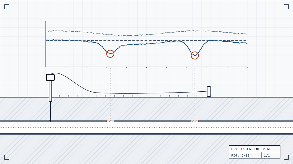
The sacrificial system told a different story. With the anodes wired straight to the pipe, a well coated line should read around -1 V or more negative; several test stations read between about -90 and -400 mV. At those locations the insulating flange kits were missing or had failed, or the pipe touched aboveground steel, so the anodes were spending themselves on plant grounding. Some risers also wore thermal blankets with a metallic mesh wrap that can bridge a flange kit. Where the soil was open, on part of the fuel gas supply, we walked an over-the-line survey at 10-foot steps: one run held between about -1,100 and -1,400 mV, while the run beyond a failed flange kit stayed near -300 mV.
The tank system was healthy, with both interior reference electrodes reading -800 mV instant-off.
The ground grid
For the grounding survey we moved the negative leads of two rectifiers to plant ground and used them as a DC source, interrupted 4 seconds on and 1 second off. With a reference electrode held in place, any jump of more than 5 mV in the off reading from one point to the next marks a break. Across 71 points, with the electrode moved once when the wire ran out, the off readings stayed within a few millivolts of their neighbors, except the circulating pump ground at the discharge structure, which was off by more than 100 mV and measured 3.2 ohms point to point. The grid as a whole measured 1.14 ohms to remote earth by fall of potential. We recommended a bonding jumper to the discharge structure.
Related services
Plant surveys of this kind are described on our page for cathodic protection potential surveys. The grounding work falls under grounding system tests.
Corrosion and CP
More projects in this practice
Wink and Sarita, TX
AC Interference Data Logging on Texas Pipelines
AC interference testing
Wickett, TX
ACVG Coating Survey of Two Gathering Lines, Wickett
ACVG survey
Eastland area, TX
Annual CP Survey and Ground Patrol of a Gas Line, Eastland Area
CP survey, ground patrol
Get your project started
We typically respond within one business day.