A Short Intro to Ripple and Transient Measuring
How engineers take ripple and transient measurements with an oscilloscope to diagnose power supply failures and verify circuit performance.
Reach out to Dreiym Engineering for any Corrosion, Electrical or Forensic Questions.
Contents
Has your power supply failed or malfunctioned? Call a forensic engineer to perform ripple and transient measuring on the supply. This short intro to transient and ripple specifications will outline the function of ripple and transient data and discuss how to measure ripple voltage effectively.
What Is Ripple Voltage?
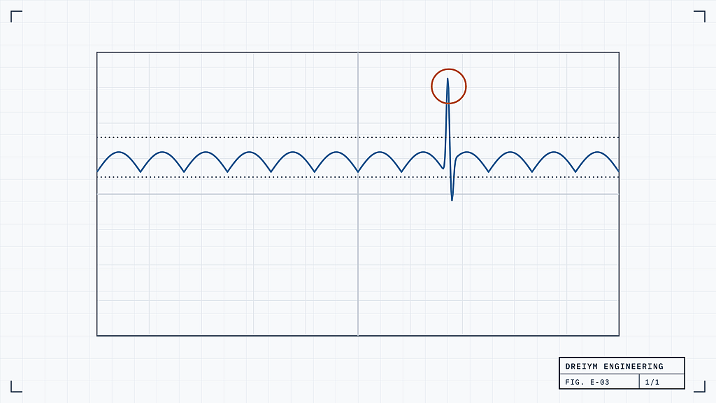
In the electronic field, ripple voltage is the residual AC (alternating current) component left on the DC (direct current) output of a power supply internally converting power from an AC source. The load, or the part of the circuit that consumes the energy, has a direct effect on the amount of ripple. Ripple measurements on a power supply generally require that the load be full to ensure accurate results.
Measuring Ripple Voltage
To get accurate and helpful results on your ripple voltage measurement, a forensic engineering service will test the power supply at full load and at a variety of input voltages. They use a single oscilloscope probe to measure, placing it across either the output capacitor or an external capacitor specified by the manufacturer.
What Is Transient Response?
The load (discussed above) is generally not at full capacity at all times. When that load changes, the output voltage changes with it, creating a transient response as the circuit adjusts. The level of transient response dictates how quickly a power supply can recover from a sudden change in electrical load.
Related service
Studies modeled in ETAP® and SKM, field testing and electrical design by licensed PEs.
Measuring Transient Response
While only one oscilloscope probe is needed to measure ripple voltage, an engineer will use two probes to get an accurate transient response reading. They place the first probe across the power supply’s output, then use the second probe with the current or with a signal simultaneous to the supply’s load change. This second probe will act as a trigger, so you can clearly see the deviation of output voltage.
Oscilloscope Techniques
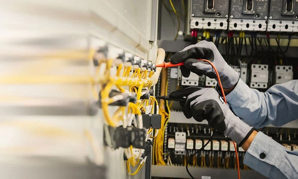
The engineer testing your power supply will use an oscilloscope to perform the reading. There are two effective techniques that minimize the ground loop the probe(s) create to ensure accurate results.
Tip and Barrel
One measurement method involves removing the ground cover and the probe’s clip so that both the tip and the barrel of the probe are exposed. The engineer attaches the exposed tip to the output voltage, angling the barrel so it touches the ground at a point near the tip.
Paperclip
This method is similar to the tip and barrel but with the addition of a tiny coil of wire around the barrel of the probe. The wire’s short lead creates a tip on the probe similar to tweezers, allowing for location flexibility while keeping the loop area small and contained.
Accurate ripple and transient measuring will help a forensic engineer determine the cause of your electrical failure. We at Dreiym Engineering hope this short intro has helped you understand these two essential circuit measurements, both available through our engineering lab testing services.