text
Investigating Electrical Failures After Flooding or Water Intrusion
Electrical
Forensic


Ufer grounding is a technique of grounding electrical systems by connecting them to a concrete-encased electrode. The term Ufer comes from the name of Herbert G. Ufer, an engineer who developed this method during World War II. Ufer grounding is also known as concrete-encased grounding or foundation grounding.
Ufer grounding was not only effective but also economical and simple to implement. Ufer estimated that the cost of grounding a depot using his method was about $60, compared to $5000 for a conventional rod and grid system. Ufer grounding also required less maintenance and testing, as the concrete electrode was protected from corrosion and physical damage.
Ufer grounding was adopted by the US Army and Navy and later by the National Electrical Code (NEC), which recognized it as an acceptable grounding method in 1968. Since then, Ufer grounding has been widely used in residential, commercial, and industrial applications, especially in areas with poor soil conductivity or high lightning activity. Ufer grounding has proven to be a reliable and safe way to protect electrical systems and personnel from electric shocks, fires, and surges.
Ufer grounding was invented as a solution to a problem faced by the US Army in the 1940s. The Army needed to protect its ammunition depots from lightning strikes, but the soil in the desert areas where the depots were located was too dry and resistant to provide good ground. Ufer discovered that concrete, which was used to build the depots, had a low resistance and could act as an effective ground electrode. He devised a way to connect the metal parts of the electrical system to the concrete foundations, creating a large and stable grounding network.
Ufer grounding has several advantages over other types of grounding, such as rod or plate electrodes. Some of the benefits are:
Ufer grounding is widely used in residential, commercial, and industrial buildings, as well as in telecommunication, power, and transportation systems. Ufer grounding is especially suitable for areas with dry, rocky, or sandy soils, where conventional grounding methods are ineffective or impractical. Ufer grounding is also recommended by the National Electrical Code (NEC) and the International Building Code (IBC) as a standard practice for grounding electrical systems.
Ufer grounding, also known as concrete-encased grounding or foundation grounding, is a method of grounding an electrical system by connecting a grounding electrode conductor to a steel rod or wire that is embedded in the concrete foundation of a building. The concrete acts as an electrolyte and provides a low-resistance path for the dissipation of fault currents and lightning surges to the earth.
According to NEC 250.52(A)(3), a concrete-encased electrode can be used as a grounding electrode for any electrical system, if it meets the following requirements:
– The electrode must consist of at least 6.0 m (20 ft) of electrically conductive steel reinforcing bars or rods of not less than 13 mm (1/2 in.) in diameter or of at least 6.0 m (20 ft) of bare copper conductor not smaller than 4 AWG.
– The electrode must be encased by at least 50 mm (2 in.) of concrete, located horizontally near the bottom or vertically within the concrete foundation or footing that is in direct contact with the earth.
– The electrode must be bonded to the grounding electrode conductor by an approved device or method, such as an exothermic weld, a listed lug, or a listed pressure connector.
If the concrete-encased electrode does not meet these requirements, it must still be bonded to the grounding system, and another grounding electrode that meets the requirements must be installed, such as a conventional ground rod
Before the concrete is poured, the ufer (concrete-encased electrode) must be inspected by a qualified Electrical Engineer or qualified Inspector to verify that it meets the requirements of the National Electrical Code (NEC). Electricians who install the ufer should never be used as the inspector; many authorities will reject that inspection.
Suppose the concrete is already poured, and the ufer is not accessible for inspection. In that case, the installer must provide documentation that proves that the ufer was installed according to the NEC. This may include photos (that meet certain strict requirements), drawings, invoices, or certificates from the manufacturer or supplier of the conductor or the concrete. The requirements of this documentation are normally such that it must be held up in court under extreme scrutiny. Just imagine someone getting shocked or electrocuted at the structure, the quality of this documentation will become important. Most electricians and builders do not have the ability to take evidence-quality photo documentation, and hiring a forensic engineer just to photograph a slab is prohibitively expensive in most cases.
Suppose the documentation is not available or sufficient. In that case, the installer and inspector must assume that the ufer does not meet the NEC requirements and install another grounding electrode that does, such as a conventional ground rod. Most times, it is the most cost-effective to simply install two supplemental ground rods, which not only meet the requirements of NEC 250.52 for most residential structures but also meet the requirements for adding a second ground rod if the first rod does not meet the 25-ohm requirement to remote earth.
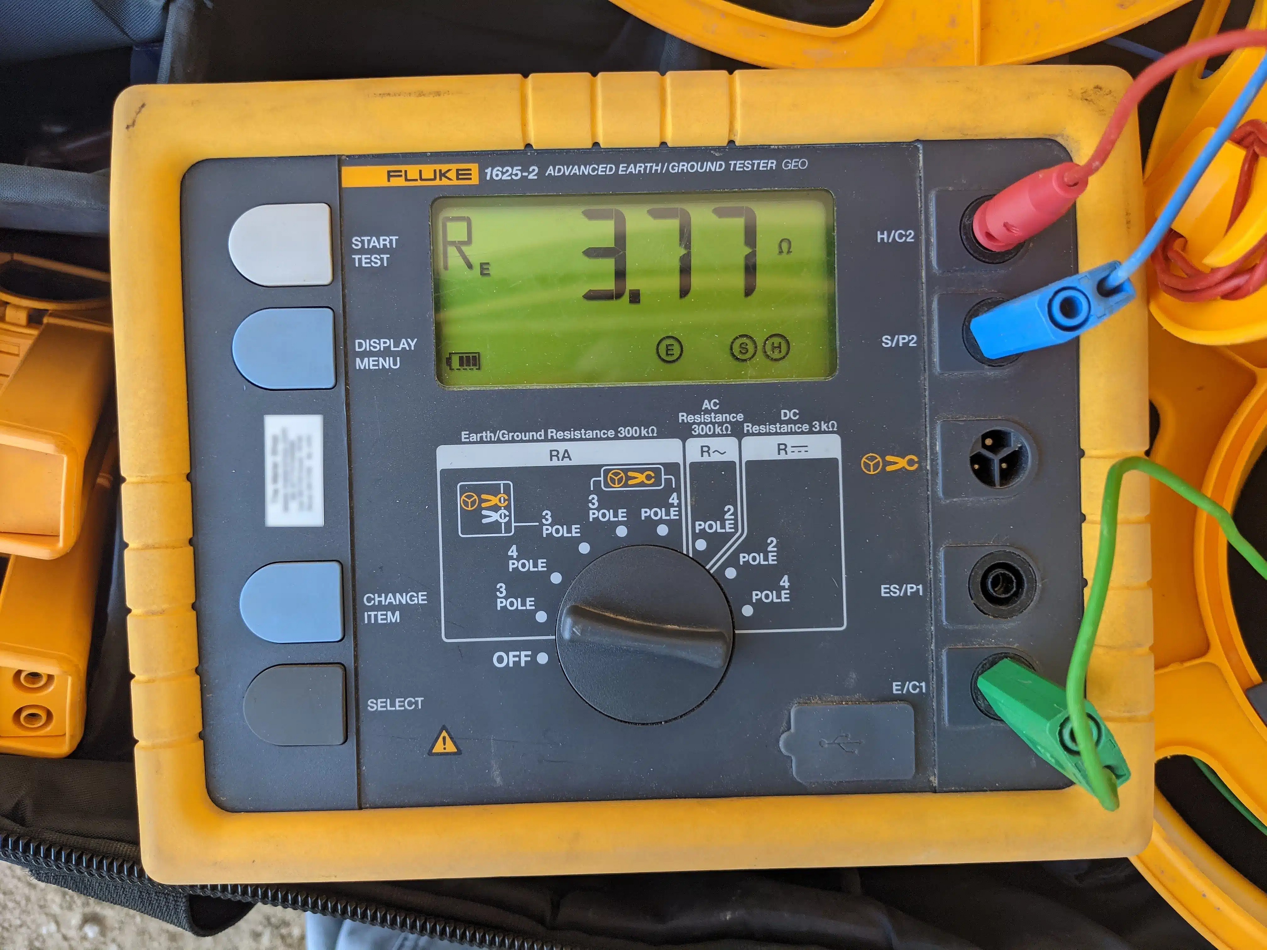
This test measures how good the electrical contact is between the electrical grounding system, through the concrete slab, and out to remote earth using the fall-of-potential method. Here, the test shows 3.77 ohms to remote earth.
Another important aspect of ufer inspections is to ensure that the slab is continuous and electrically bonded. This means that there are no breaks or gaps in the concrete that would interrupt the flow of electricity through the ufer. A discontinuous slab can reduce the effectiveness of the ufer as a grounding electrode and increase the risk of step-step potentials inside the home. Step-step potentials are voltage differences between two points on the ground that can cause electric shocks to adults, children, or animals walking on them.

This test measures the strength of a signal walking over a large commercial slab. Here, the depth of a metallic structure is measured inside the slab at a specific location.
To verify the continuity of the slab, Dreiym Engineering can perform a toning test using a tone generator and a probe. The tone generator sends a signal through the ufer, and the probe detects it on the other end and throughout the slab. If the signal is clear and consistent, it means that the slab is continuous and well-bonded. If the signal is weak or intermittent, it means that there are breaks or gaps in the slab that need to be repaired or bridged with copper wire. Dreiym Engineering can also identify the locations of the breaks or gaps and provide solutions to fix them.
If you do not have the documentation or inspections to prove that the ufer meets the NEC requirements, you must install another type of grounding electrode that does. One of the most common and economical options is to install a ground rod. A ground rod is a metal rod that is driven into the earth at least 8 feet deep. The rod must be made of copper or galvanized iron, and must have a minimum diameter of 5/8 inch for copper or 3/4 inch for galvanized iron. The rod must be connected to the grounding electrode conductor with an approved clamp or connector. The connection must be accessible for inspection.
According to the NEC, a single ground rod is acceptable as a grounding electrode if it has a resistance to remote earth of 25 ohms or less. However, this resistance can vary depending on the soil conditions and moisture level. Therefore, it is recommended to measure the resistance of the ground rod using a device called a ground resistance tester. The tester applies a known voltage and current to the ground rod and measures the resulting voltage drop.
If the resistance of the ground rod is higher than 25 ohms, you must install a second ground rod at least 6 feet away from the first one, and connect them in parallel with the grounding electrode conductor. The NEC does not require you to measure the resistance of the second ground rod, as long as you install it according to the code specifications. However, it is good practice to verify that the resistance of the combined ground rods is lower than the resistance of the single ground rod.
Dreiym Engineering can help you with the testing of ground rods for your project. We have the equipment and expertise to perform accurate and reliable ground resistance measurements. We can also advise you on the optimal location and spacing of the ground rods, and ensure that they are properly connected to the grounding system. We can provide you with a report that documents the results of our tests and the compliance of your ground rods with the NEC standards.
Ufer inspections are crucial to ensure the safety and reliability of your electrical system. A ufer that does not meet the NEC standards can compromise the grounding of your system, which can lead to electrical hazards, equipment damage, or power outages. That’s why you need a trusted partner like Dreiym Engineering to perform ufer inspections for your project.
Dreiym Engineering has the expertise and experience to conduct ufer inspections before or after the concrete is poured. We have conducted hundreds of inspections on ufer grounding systems. We have qualified Electrical Engineers and Inspectors who are familiar with the NEC requirements and the best practices for ufer installation. We can verify that your ufer meets the specifications for size, length, location, encasement, and connection to the grounding electrode conductor. We can also provide documentation to support our findings and recommendations.
If your concrete is already poured and your ufer is not accessible for inspection, we can help you obtain or prepare the necessary documentation to prove that your ufer was installed according to the NEC. We can review your photos, drawings, invoices, or certificates and ensure that they meet the strict criteria for acceptance. We can also test your grounding system for resistance and continuity and provide a report of our results.
At Dreiym Engineering, we care about your safety and satisfaction. We offer ufer inspections at competitive prices and flexible schedules. We work with contractors, homeowners, architects, and engineers to ensure that your electrical system is grounded properly and complies with the NEC. Contact us today to schedule your ufer inspection or to learn more about our services.
Always consult your licensed electrical installer/design professional to ensure all requirements of the NEC and other applicable codes are met.


