Grounding Electrodes and Ground Bonding Systems: How to Test Them and Why It Matters
Learn the two tests every ground system needs: fall-of-potential for grounding electrodes and clamp-on AC impedance for bonding, and why both matter.
Contents
Grounding electrodes and ground bonding systems are essential components of electrical installations that provide safety and protection for people and equipment. The grounding electrode system limits the voltage imposed on the installation by lightning, line surges and unintentional contact with higher-voltage lines, and stabilizes the system voltage to earth (NEC® 250.4(A)(1)). It is the equipment grounding conductor and the grounded conductor, not the earth, that carry ground-fault current back to the source so the overcurrent device operates: NEC 250.4(A)(5) states expressly that the earth shall not be considered as an effective ground-fault current path. A low electrode resistance therefore improves lightning and surge performance and voltage stability; it does not clear faults. Ground bonding systems are conductive wires or bars that connect the grounding electrodes to the equipment and enclosures that need to be grounded. They ensure that all the grounded parts have the same potential and reduce the risk of electric shock and fire. While the systems are very simple, the terminology can take some to master. A more complete understanding can be obtained in the National Electrical Code (NEC) Chapter 250.
Want your electrodes and bonds measured rather than assumed? See our ground testing services for resistance-to-earth and continuity testing at new and existing sites.
A field example from our work: Soil Resistivity Tests for Grounding Design, Comfort and Midlothian
Testing a Grounding Electrode’s Remote Earth Resistance
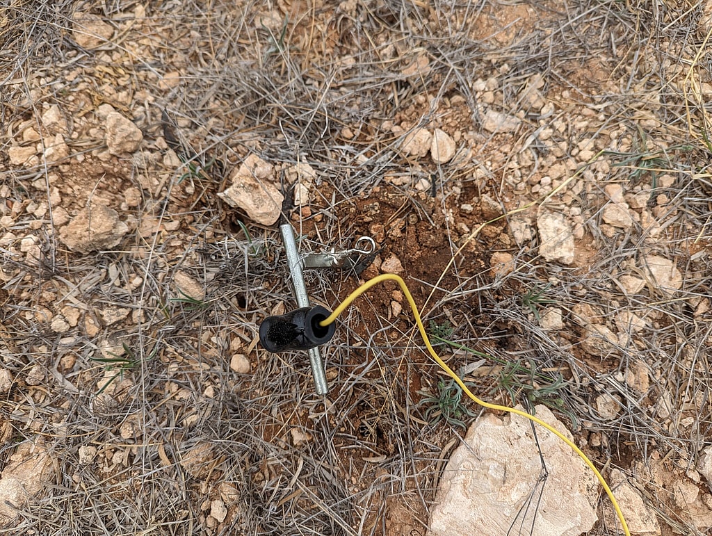
One of the most important parameters of a grounding electrode is its remote earth resistance, which is the resistance between the electrode and a point far away from it in the earth. The lower the remote earth resistance, the better the grounding electrode can dissipate fault currents and prevent over-voltages. The remote earth resistance depends on several factors, such as the soil resistivity, the depth and length of the electrode, the moisture and temperature of the soil, and the presence of other nearby electrodes or conductors.
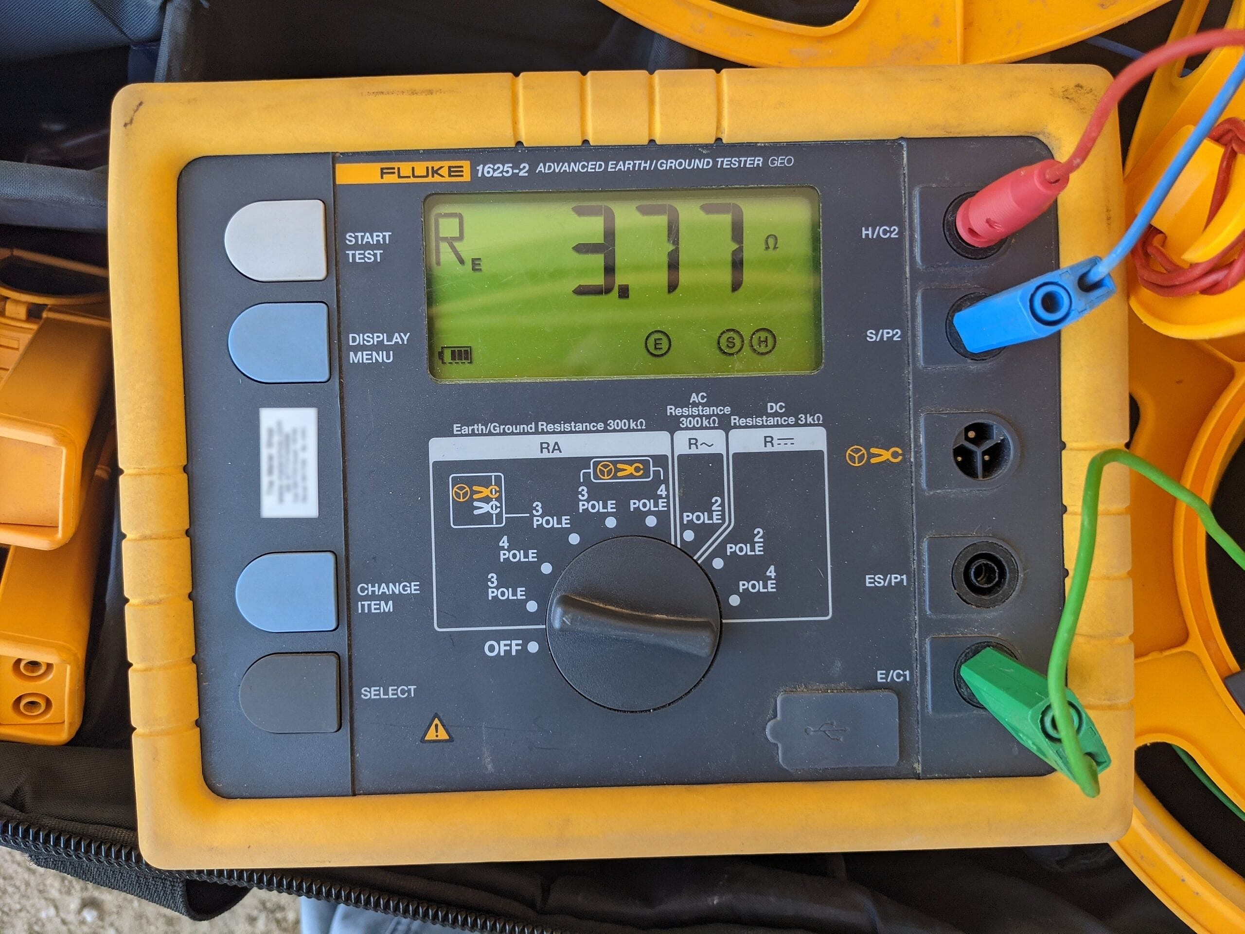
To measure the remote earth resistance of a grounding electrode, a common method is the fall-of-potential method, which uses a test instrument, a current probe, and two auxiliary electrodes. The test instrument injects a known current into the grounding electrode and the current probe and measures the voltage drop across the grounding electrode and one of the auxiliary electrodes. The remote earth resistance is calculated by dividing the voltage drop by the injected current. The other auxiliary electrode is used to verify that the measured voltage drop is independent of its position, which indicates that the remote earth resistance is accurate.
What Is a Ground Test Using an Auxiliary Current Electrode?
It is the fall-of-potential test, also called the three-point method, described in IEEE Std 81. The tester drives a known current between the electrode under test and an auxiliary current electrode placed well away from it, and a potential probe moved between the two measures the voltage. Resistance is that voltage divided by the current. When the current electrode is far enough away, the readings level off. For a single small electrode in uniform soil, the plateau falls with the potential probe at about 62 percent of the distance to the current electrode, and that plateau value is the electrode resistance.
Related service
Ground Testing and Commissioning
Fall of potential, clamp-on, soil resistivity, bonding
Testing AC Impedance of a Ground Bonding System
Another important parameter of a ground bonding system is its AC impedance, which is the opposition to the flow of alternating current in the system. The lower the AC impedance, the better the ground bonding system can equalize the potentials of the grounded parts and reduce the noise and interference in the system. The AC impedance depends on several factors, such as the resistance, inductance, and capacitance of the ground bonding conductors, the frequency of the current, and the configuration and layout of the system.
To measure the AC impedance of a ground bonding system, a common method is the clamp-on method, which uses a test instrument with a split-core current transformer. A clamp-on (stakeless) tester induces a known voltage into the ground loop with one toroid and measures the resulting current with a second toroid, computing the loop resistance as R = V/I without probes or disconnection. Because it measures a complete loop, it is valid only where the electrode under test is one of several grounds in parallel and the return path is genuinely through earth; it cannot measure an isolated electrode or verify a new installation, and it is corrupted, not improved, by a low-resistance metallic return that bypasses the soil. Where a single electrode must be verified, use the fall-of-potential or a selective method instead.
Contrasting the Two Tests and Their Importance
The two tests described above are different in their purposes, methods, and results. The test for the remote earth resistance of a grounding electrode is intended to evaluate the performance of the electrode in dissipating fault currents and preventing overvoltages. The test for the AC impedance of a ground bonding system is intended to evaluate the performance of the system in equalizing the potentials of the grounded parts and reducing the noise and interference. The test for the remote earth resistance uses a fall-of-potential method with two auxiliary electrodes, while the test for the AC impedance uses a clamp-on method with a split-core current transformer. The test for the remote earth resistance gives a value in ohms, while the test for the AC impedance gives a value in ohms or milliohms, depending on the frequency of the current.
Both tests are important for ensuring the safety and reliability of electrical installations. A grounding electrode with a high remote earth resistance may not be able to divert fault currents effectively and may cause overvoltages that can damage the equipment and endanger the people. A ground bonding system with a high AC impedance may not be able to maintain the same potential among the grounded parts and may cause electric shock hazards and signal distortions. Therefore, both tests should be performed regularly and according to the standards and codes of the industry.
Why you must perform both tests
Performing both tests on a ground system is essential for safety because they complement each other and provide a comprehensive assessment of the ground system’s functionality. A grounding electrode with a low remote earth resistance can ensure that fault currents are dissipated effectively and over-voltages are prevented, but it may not be sufficient to protect the equipment and personnel from electric shock hazards and signal distortions if the ground bonding system has a high AC impedance. Conversely, a ground bonding system with a low AC impedance can ensure that the potentials of the grounded parts are equalized and the noise and interference are reduced, but it may not be sufficient to protect the equipment and personnel from overvoltages and fire hazards if the grounding electrode has a high remote earth resistance. Therefore, both tests are necessary to verify that the ground system meets the safety and performance requirements of the industry.
Dreiym Engineering can help by providing the expertise needed for these grounding system tests. Our team of engineers has extensive experience and knowledge in performing both the remote earth resistance test and the AC impedance test using the latest equipment and techniques. We can conduct these tests according to the standards and codes of the industry and provide you with accurate and reliable results. We can also help you interpret the results and recommend the best solutions to improve your ground system‘s performance and safety. Contact us today to schedule an appointment or request a quote.