Selected Projects
Soil Resistivity Tests for Ground System Design at Three Sites, Cotulla, Pleasanton and Victoria (2024)
We typically respond within one business day.
Project at a glanceDE-PRJ-8826
- Practice
- Electrical power
- Location
- Cotulla, Pleasanton and Victoria, TX
- Service
- Soil resistivity testing
- Client
- Confidential
Soil Resistivity Tests for Ground System Design at Three Sites, Cotulla, Pleasanton and Victoria (2024)
A ground system is designed to reach a target resistance to remote earth, and how much copper that takes depends on the soil. In May and June 2024, geotechnical firms working on three project sites in South Texas asked us for that number, and we ran soil resistivity tests for grounding design at the three sites.
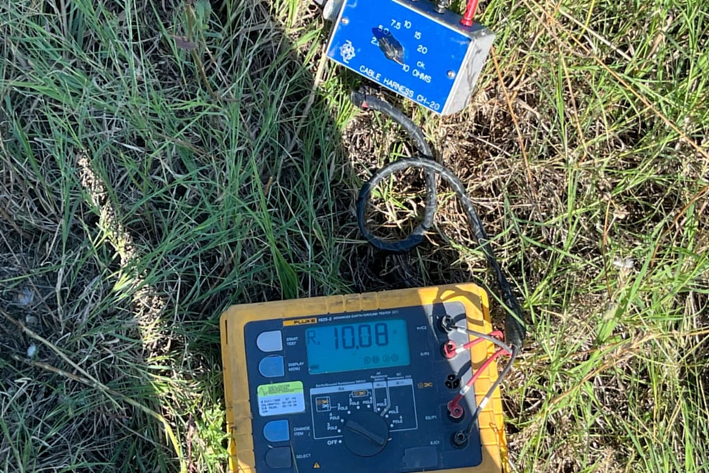
The method
Each test used the Wenner four-pin method (ASTM G57): four steel pins in a line at equal spacing, with current passed through the outer two and voltage read across the inner two. The reading is usually taken as the average resistivity down to a depth roughly equal to the spacing, a field rule of thumb. We used spacings of 2.5, 5, 7.5, 10, 15 and 20 feet. The Barnes layer method then turns those averages into the resistivity of each layer. For grounding design the top 10 feet matter most. At every site we ran the array in more than one direction, because buried metal or a change in the ground shows up as a reading that shifts when the array turns. The soil was dry at all three sites, which tends to read higher than the same soil after rain.
Three sites
Near Cotulla, two arrays, east to west and then turned 90 degrees, put the top 10 feet between 1,000 and 6,000 ohm-cm. Near Pleasanton, tested the same day, four arrays, two in each direction, gave 100 to 3,000 ohm-cm. Near Victoria in late June, three arrays, the first square to a farm road, the second turned 90 degrees and the third turned another 45 degrees and moved to the southeast, gave 100 to 2,000 ohm-cm.
The spread inside each site is the reason a single average is not enough. The ground system designer for each site would use these layer values together with the boring logs to choose rod depths and how much conductor to bury.
Related services
Soil testing for ground systems is part of our grounding system tests. The same field method supports soil corrosivity analysis.
Electrical power
More projects in this practice
Norman, OK
Airport Grounding Testing, Norman
Ground testing
Temple, Grand Prairie and Humble, TX
Arc Flash Studies at Manufacturing Plants in Temple, Grand Prairie and Humble
Arc flash, coordination
Hattiesburg, MS, plus AZ, WA and TX
Arc Flash Studies for Four Plants in Four States
Arc flash, labels
Get your project started
We typically respond within one business day.