Selected Projects
Airport Grounding-System Testing, Norman, Oklahoma (2025)
We typically respond within one business day.
Project at a glanceDE-PRJ-8120
- Practice
- Electrical power
- Location
- Norman, OK
- Service
- Ground testing
- Client
- Confidential
Airport Grounding-System Testing, Norman, Oklahoma (2025)
We tested an airport grounding system in Norman, Oklahoma, in 2025. It was an electrical engineering project to check the system’s condition and how well it was performing. Client details are confidential.
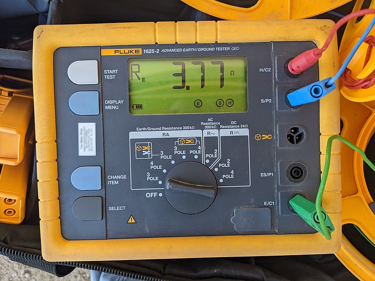
A fall of potential test. You can’t judge a ground by looking at the connection, so it has to be measured.
What wears a ground down
Almost none of a grounding system is visible. Ground rods, buried conductors, and bonding connections spend their service lives underground or inside equipment enclosures. Corrosion, loose hardware, changes in the soil, and earlier construction work can all degrade them over time without anyone noticing. A facility can run for years on a compromised ground with no obvious symptoms, until a fault or a lightning strike finds the weak point. Measuring is the only way to know how well a grounding system is working. At an operating facility, the testing has to be planned and carried out carefully so normal activity can go on.
What depends on the ground at an airport
An airport needs a dependable ground for several reasons. It sits on open terrain, with tall structures such as masts and antennas, and that raises its exposure to lightning. A low-resistance connection to earth is what carries that energy away from buildings and equipment. Navigational aids, airfield lighting, radio, and communications systems are all sensitive electronics. If the grounding and bonding aren’t sound, surges and differences in ground potential can damage components or disrupt the signals flight operations depend on. Grounding is a personnel safety system as well. It gives fault current a deliberate path back to the source, so protective devices operate quickly and exposed metal parts don’t stay energized at dangerous touch voltages.
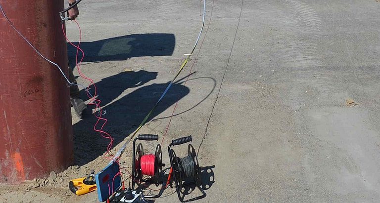
Wire reels and the kind of instruments used in ground resistance testing. The test leads have to be run well away from the ground system, so the wire comes on reels.
Fall of potential and in-service testing
A grounding measurement doesn’t tell you much unless the method is reported with it. The reference method for electrode resistance is fall of potential, described in IEEE® Std 81. Current is driven between the system under test and a remote probe, the potential is read at intervals between them, and the resistance is taken from the plateau, where the readings flatten out. Reading at 62 percent of the distance to the current probe is a common shortcut to the plateau. It only works with the probe far enough out, in reasonably uniform soil. On a large or irregular grid, a probe set too close reports a comfortably low number that the system doesn’t have.
Where shutting a facility down isn’t an option, an electrode bonded into a multi-grounded system can’t be isolated for a classic test. Selective or clamp-on methods are used instead, reading just the branch of interest while the system stays in service. Soil resistivity is a separate measurement, typically made with the four-pin Wenner method in ASTM® G57 at several pin spacings. It explains the resistance reading and predicts how much seasonal moisture will move it. Continuity and bonding checks between structures, equipment, and lightning protection components are needed too. Resistance to earth says nothing about whether those pieces are still tied together. If the method, the probe geometry, the weather, and the season are recorded with each reading, the measurements become a baseline the next test can be compared against.
What the Norman testing covered
Our field team tested the system with recognized industry methods. Most of the work was measuring the grounding electrodes’ resistance to earth, checking point-to-point continuity between bonded components, and inspecting the connections we could reach for corrosion, damage, and loose hardware. We logged the test locations and readings, so the next round of testing has a baseline to measure against. A licensed Professional Engineer oversaw the testing and the report we delivered, which gives the measured values along with our observations and recommendations.
When was your ground last tested?
The ground protects everything else on a site. People rely on it, and so do the structures and electronics. It also degrades without any outward sign, which makes it easy to take for granted. Testing at regular intervals means you’re working from measured values instead of assumptions. It catches deterioration before something fails, and it gives you the records you need to plan maintenance. If your facility has never had its grounding measured, or hasn’t been retested in years, our grounding system testing services can tell you where things stand. This project is one example of our electrical engineering work in Oklahoma.
Electrical power
Related projects
El Paso, TX
Power Station Grounding Survey, El Paso
Grounding
San Antonio, TX
Ground Resistance Tests at a Distribution Center, San Antonio
Ground resistance testing
Texas Hill Country
Grounding and Infrared Program, Hill Country
Grounding, infrared
More work in: Oklahoma
Get your project started
We typically respond within one business day.