Electrical Interactive
The Steps To Complete an Arc Flash Analysis
Learn the arc flash analysis steps engineers follow (gathering one-lines, field verification, modeling, and labeling) plus OSHA and NFPA 70E requirements.
Reach out to Dreiym Engineering for any Corrosion, Electrical or Forensic Questions.
Contents
The importance of a company’s workplace safety starts at the top. When business owners and managements prioritize onsite safety and preventative measures, their employees are likely to, as well. Not only is workplace safety imperative to the wellbeing of onsite staff, but it also plays a critical role in protecting your property from preventable damage and disaster. An arc flash analysis is one of those measures.
Once the first analysis is done, regular arc flash studies keep it accurate as your system changes.
Especially at a large corporation, attention to safety details is a must, so much so that there’s an organization to verify the health and safety of your company, the Occupational Safety and Health Administration (OSHA). OSHA minds the electrical safety of companies, too, including their protection against arc flashes. Your business must invest in an arc flash analysis to reduce the risk of an arc flash and all its potential damage. Though arc flash consultants ought to perform these complex analyses, you can review the steps to complete an arc flash analysis, the importance of getting one, and OSHA’s arc flash requirements, to gain familiarity with the process.
What Is an Arc Flash?
An arc flash is the term used when poor electrical resistance connections within an electrical system project unwanted electrical discharge through the atmosphere and toward another voltage phase or the ground. In return, the electric system’s environmental temperature and pressure rise significantly. Too much heat and pressure result in what’s known as an “arc blast,” or an electrical explosion.
The Detrimental Dangers of Arc Flashes
If the idea of an electrical explosion isn’t enough to convince you to invest in an arc flash analysis, here are a few unfortunate outcomes that may come from an arc blast occurrence.
- Electrical fires
- Pressure waves
- Flying shrapnel
Each of these effects of an arc flash can cause serious harm to employees within its boundaries (in dire cases, death) and considerable damage to your property. Because these types of explosions happen without notice, it’s vital to adopt as many preventative measures as possible.
The Most Common Causes of Arc Flash in Electrical Systems
For something so detrimental to your business, you’re probably curious as to what causes an arc flash. Below, Dreiym Engineering lists the most common causes of arc flash in corporate electrical systems:
- Faulty electrical equipment and accessories
- Hindered insulation
- Inadequate installation and maintenance
- High-voltage cables
- Static electricity
- Electrical equipment encounters with water
- Corroded cables
- Exposed live wires or conductors
- Loose connections
The OSHA, Arc Flashes, and the Evolution of Requirements
Upholding safety standards for your employees isn’t simply an altruistic move; it’s a legally required one. The OSHA strives to ensure that all companies provide adequate working conditions for their staff through training, outreach, education, and assistance.
Should your company violate any of the health and safety requirements set by OSHA, it becomes subject to steep fines, a damning reputation, and potentially even time in prison. In addition to the OSHA, the National Fire Protection Association (NFPA), the Institute of Electrical and Electronics Engineers (IEEE), and the National Electrical Safety Code® also have their demands for businesses to abide by:
OSHA Standards for Arc Flash
- OSHA 29 CFR 1910.132(d)(1)
- OSHA 29 CFR 1910.332(b)(1)
- OSHA 29 CFR 1910.333(b)(2)(iv)(B)
- OSHA 29 CFR 1910.335(a)(1)(i)
- OSHA 29 CFR 1910.335(a)(1)(v)
NFPA Code 70E’s Articles That Apply for Arc Flash
- Article 130.5
- Article 130.7
NEC (NFPA 70) Articles That Apply To Arc Flash
- Article 110.16(A)
- Article 110.16(B)
For utility installations covered by the NESC® (IEEE C2) rather than the NEC®, the arc flash assessment requirement appears in Rule 410.A.3.
IEEE 1584
The IEEE 1584 is The Guide for Performing Arc Flash Hazard Calculations. It has evolved since its inception in 2002 to ensure arc flash analyses’ accuracy. The IEEE 1584 provides helpful information for identifying electrode configurations, voltage ranges, enclosure sizes, and other necessary measurements for the evaluation. To see how those inputs change the result for one piece of equipment, try our arc flash calculator.
What Are the Steps To Completing an Arc Flash Analysis?
With an appreciation for the preventative necessity of an arc flash analysis, Dreiym Engineering now looks at the steps to complete an arc flash analysis that electrical professionals typically follow for an accurate assessment.
Gather Existing Electrical Layouts
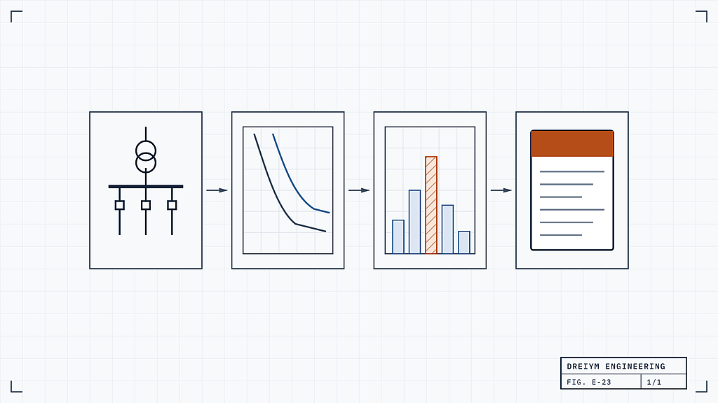
The first step to any arc flash analysis is gathering all of the existing electrical layout documents. You’ll need to relay documents such as blueprint drawings of floor plans and riser one-line diagrams to the team or individual performing the analysis.
If you currently do not have electrical layout documentation, you’re going to need to have it made. Every thorough field survey requires accurate documentation of electrical one-lines. An electrical one-line document serves as a road map of your facility’s electrical distribution, a must-have for a successful arc flash analysis.
Get Your Layout Documentation Field Verified
Any outlines and drawings must get verified before getting processed by arc flash analysis software. To verify the documents, professionals will perform a field survey of each site that’s getting assessed.
In order to produce the most accurate electrical one-line, electrical consultants will then note any missing information on the original one-line. Data collection requires access to nameplate data, trip-unit settings, and conductor sizes and lengths. Wherever cover removal is needed, the equipment should be placed in an electrically safe work condition in accordance with NFPA 70E 120.6 before the covers come off; for this reason the field survey is best scheduled with a planned outage. Where a shutdown is not feasible because of equipment design or operational limitations, the survey step is treated as energized work: it is justified in writing under NFPA 70E 130.2, authorized by an energized electrical work permit, performed only by qualified persons, and executed with the shock and arc-flash PPE established by a preliminary risk assessment.
Upload Documentation Into Arc Flash Analysis Software
Once the one-line is appropriately updated, consultants can submit the documents into an arc flash analysis software. Electrical consultants will perform the following tests with the trusted software.
- Perform a Short Circuit Assessment
- Complete a Coordination Study
- Evaluate for Arc Flash
Comprehensive System Evaluation
Once each analysis is executed, your hired professional will create and apply arc flash labels for your equipment. In addition, you and they will train staff on what the labels mean and proper electrical safety procedures.
Arc flash incident energy calculator (IEEE 1584-2018)
Estimate the incident energy and the arc flash boundary of three-phase equipment from 208 V to 15 kV with the IEEE 1584-2018 model, and see the boundary drawn around the equipment. Pick a quick start or enter your own equipment; the answer updates as you type. Every step is shown.
The calculator needs JavaScript. The method, typical values and the range of the model are below.
Quick start Fills in the form. Change anything after.
Result
Above 1.2 cal/cm² at 18 in
Screening estimate: incident energy 2.7 cal/cm² (11.1 J/cm²) at 18 in; arc flash boundary 2 ft 6 in (750 mm). Higher of the two cases: the arcing current (22.03 kA, cleared in 50 ms).
- Incident energy at the working distance
- 2.7 cal/cm²
- Arc flash boundary
- 2 ft 6 in
- Arcing current used
- 22.03 kA, 50 ms
What it means
Screening estimate. Not for equipment labels or PPE selection. This tool gives no PPE category. Arc flash studies give values you can act on, or ask an engineer.
Full results and steps
| Case | Current | Clearing time | Incident energy | Arc flash boundary |
|---|---|---|---|---|
| Arcing current | 22.03 kA | 50 ms | 2.7 cal/cm² (11.1 J/cm²) | 2 ft 6 in (750 mm) |
| Reduced arcing current | 19.32 kA | 50 ms | 2.3 cal/cm² (9.8 J/cm²) | 2 ft 3 in (700 mm) |
Inputs used
480 V, bolted fault current 30 kA, VCB, gap 25 mm, working distance 18 in, enclosure 14 in × 12 in × 10 in (height × width × depth), 60 Hz.
- Step 2, intermediate arcing current at 600 V (Equation 1): 24.123 kA
- Step 3, arcing current at 480 V (Equation 25): 22.032 kA
- Step 4, variation factor (Equation 2): VarCf = 0.247; reduced arcing current = 22.032 × (1 − 0.5 × 0.247) = 19.317 kA
- Step 5, typical enclosure (not shallow: the depth is more than 8 in (203.2 mm)): Width1 = 20.000 in, Height1 = 20.000 in, EES = 20.000 in, CF = 1.000 (Equations 11 to 14)
- Step 6, incident energy at the arcing current, 50 ms (Equation 6): 11.145 J/cm²
- Step 8, arc flash boundary at the arcing current (Equation 10): 753.1 mm
- Step 9, reduced arcing current, 50 ms (Equations 6 and 10, Iarc_600 in the k3 term): 9.827 J/cm², boundary 696.0 mm
- Step 10, reported: incident energy 11.145 J/cm² = 2.664 cal/cm² (arcing current); arc flash boundary 753.1 mm (arcing current)
Notes
- You entered the same clearing time for both currents. For most devices the time at the lower current is the same or longer; read both from the device curve.
- Read each time from the time-current curve of the protective device that clears a fault at this equipment, usually the device on its supply side, at the current shown: the total clearing time (for a fuse its total clearing curve, for a circuit breaker including its opening time, for a relay the relay time plus the breaker opening time). If the arcing current falls below an instantaneous pickup, the time comes from the slower part of the curve. A study also checks other operating conditions and devices that see only part of the current.
- This is a screening estimate, not a value for an arc flash label.
- Three-phase AC systems only.
- Values are shown rounded; the calculation carries full precision.
Need incident energy values you can act on?
Dreiym's licensed Professional Engineers perform arc flash studies to IEEE 1584 and NFPA 70E, PE-stamped where required: a field walk-down, short-circuit and coordination models, incident energy at every bus, and the equipment labels.
Safety and limits
Not for equipment labels or PPE selection. NFPA 70E requires the arc flash risk assessment to be done by qualified persons and kept current; see NFPA 70E 130.5 for what incident energy and the arc flash boundary mean. This tool gives no PPE category.
Screening tool: Screening estimate for education and planning. Not an engineering study, not a substitute for an analysis by a licensed Professional Engineer, and not for equipment labeling or safety decisions.
How the IEEE 1584-2018 method works
- Arcing current: the model computes the arcing current at 600 V, 2,700 V and 14,300 V from the bolted fault current and the gap (Equation 1) and interpolates to the system voltage (Equations 16 to 18); at 600 V and below it uses its own formula (Equation 25).
- Reduced arcing current: the arcing current varies, so the model also lowers it by a variation factor that depends on the voltage and the electrode configuration (Equation 2). A lower current can take longer to clear, so incident energy is computed for both currents, each with its own clearing time, and the higher result is reported.
- Enclosure: for enclosed configurations the enclosure size changes the energy through a correction factor (Equations 11 to 15). Below 600 V, an enclosure under 20 in high and wide and 8 in deep or less counts as shallow.
- Incident energy at the working distance comes from the arcing current, the bolted fault current, the gap, the clearing time and the enclosure factor (Equations 3 to 6); above 600 V it is interpolated between the model voltages (Equations 19 to 21).
- Arc flash boundary: the distance at which the incident energy falls to 1.2 cal/cm² (5.0 J/cm²) (Equations 7 to 10, interpolated with Equations 22 to 24).
- IEEE 1584-2018 notes that in three-phase systems of 240 V or less with available short-circuit current under 2,000 A an arc is less likely to sustain, but still possible. It is not an exemption. The 2002 edition's exclusion of equipment below 240 V fed by a transformer under 125 kVA was removed in 2018.
- Read each time from the time-current curve of the protective device that clears a fault at this equipment, usually the device on its supply side, at the current shown: the total clearing time (for a fuse its total clearing curve, for a circuit breaker including its opening time, for a relay the relay time plus the breaker opening time). If the arcing current falls below an instantaneous pickup, the time comes from the slower part of the curve. A study also checks other operating conditions and devices that see only part of the current.
Typical values and model ranges
| Equipment class | Typical gap (mm) | Enclosure | Typical working distance |
|---|---|---|---|
| 600 V and below | |||
| Low-voltage switchgear | 32 | 508 × 508 × 508 mm (20 × 20 × 20 in) | 609.6 mm (24 in) |
| MCC or panelboard, 8 in deep or less | 25 | 355.6 × 304.8 × ≤ 203.2 mm (14 × 12 × ≤ 8 in) | 457.2 mm (18 in) |
| MCC or panelboard, deeper than 8 in | 25 | 355.6 × 304.8 × > 203.2 mm (14 × 12 × > 8 in) | 457.2 mm (18 in) |
| Cable junction box, 8 in deep or less | 13 | 355.6 × 304.8 × ≤ 203.2 mm (14 × 12 × ≤ 8 in) | 457.2 mm (18 in) |
| Cable junction box, deeper than 8 in | 13 | 355.6 × 304.8 × > 203.2 mm (14 × 12 × > 8 in) | 457.2 mm (18 in) |
| Above 600 V | |||
| 5 kV motor control center | 104 | 660.4 × 660.4 × 660.4 mm (26 × 26 × 26 in) | 914.4 mm (36 in) |
| 5 kV switchgear, 36 in cubicle | 104 | 914.4 × 914.4 × 914.4 mm (36 × 36 × 36 in) | 914.4 mm (36 in) |
| 5 kV switchgear, 45 × 30 in cubicle | 104 | 1,143 × 762 × 762 mm (45 × 30 × 30 in) | 914.4 mm (36 in) |
| 15 kV motor control center | 152 | 914.4 × 914.4 × 914.4 mm (36 × 36 × 36 in) | 914.4 mm (36 in) |
| 15 kV switchgear | 152 | 1,143 × 762 × 762 mm (45 × 30 × 30 in) | 914.4 mm (36 in) |
| Input | Range |
|---|---|
| System voltage, three-phase, line-to-line | 208 to 15,000 V |
| Bolted fault current, 600 V and below | 0.5 to 106 kA |
| Bolted fault current, above 600 V | 0.2 to 65 kA |
| Gap, 600 V and below | 6.35 to 76.2 mm (0.25 to 3 in) |
| Gap, above 600 V | 19.05 to 254 mm (0.75 to 10 in) |
| Working distance | 304.8 mm (12 in) or more |
| Frequency | 50 Hz or 60 Hz |
| Enclosure height (VCB, VCBB, HCB) | above 1,244.6 mm (49 in) the correction uses 1,244.6 mm. This tool also requires 355.6 mm (14 in) or more for a shallow enclosure: a tool limit that follows ETAP's recommended range, not a model range |
| Enclosure width (VCB, VCBB, HCB) | at least 4 × the gap; above 1,244.6 mm (49 in) the correction uses 1,244.6 mm |
Sources
Sources: the IEEE Std 1584-2018 model (Equations 1 to 25, Tables 1 to 10) as reproduced and cross-checked in public references: L. Yip, arcflash (open-source implementation); J. Grimard, arc-flash-calculator (open source); Engineers Edge IEEE 1584-2018 reference pages; Turn2Engineering arc flash calculator; worked examples from the Arc Flash Forum (brainfiller.com), Allumiax and arcflashcalculator.com; EasyPower®, ETAP® and SKM summaries of the model ranges and the two-case rule; J. Phillips (brainfiller.com) and e-Hazard on the 2018 low-voltage text; NFPA 70E 130.5; NIST SP 811 (1 in = 25.4 mm, 1 cal = 4.184 J).
Cite or share this tool
Dreiym Engineering. Arc flash calculator. Method: IEEE 1584-2018. https://www.dreiym.com/arc-flash-calculator-ieee-1584/
Instructors and shops are welcome to link to this tool or put its address on a handout. It is free, needs no sign-up and works on a phone.
Link copied.Citation copied.The copy did not work. The text is selected, so copy it with your device.AccessedThe Benefits of Investing in an Arc Flash Analysis for Your Company
- Maximized safety of your employees and any facility visitors.
- Optimal protection of company equipment and property.
- Helps your company maintain compliance with NFPA, NESC, and OSHA, reducing the risk of violations and their fines.
They Ensure Your Facility Is in Compliance
There are many regulations for electrical safety in different industries. If your facility works with heavy machinery or large equipment, there are likely more in-depth requirements that your electrical system must meet.
An arc-flash risk assessment and incident energy analysis are one required element of an electrical safety program, not a guarantee of compliance: OSHA also requires a documented PPE hazard assessment under 29 CFR 1910.132(d), safe work practices under 29 CFR 1910.333, safeguards and alerting techniques under 1910.335 and training under 1910.332, while NFPA 70E requires a written electrical safety program (110.5) and equipment labeling (130.5(H)), and NEC 110.16 requires arc-flash marking on the installation. NFPA 70E 130.5 requires the incident energy analysis to be updated when the electrical system changes in a manner that affects the results, and reviewed for accuracy at intervals not exceeding five years. A study quantifies and documents the hazard so it can be controlled; it does not by itself prevent an arc flash.
They Catch Problems Early
When your facility gets arc flash studies on a regular basis, it can help prevent larger maintenance costs down the road. Catching any problems or high-risk areas early on means you can invest in prevention methods. Prevention is often much more cost-effective than fixing or repairing an issue that’s already spiraled out of control.
Examples from our project write-ups include a federal campus in Houston, modeled in six operating configurations and updated in 2024, a mine and mill in Marble Falls, Texas, and an industrial facility with 34.5 kV service in Bayou Vista, Louisiana.
At Dreiym Engineering, we are committed to maximizing your facility’s safety. We have a variety of electrical services to choose from, on top of corrosion and forensic evaluations. Whatever your needs, our team of consultants is here to provide. Contact us today to learn more.
