About
Engineering for Telecommunications Sites
We typically respond within one business day.

Why telecom sites keep taking damage
A communication tower is often the tallest structure for miles, and every copper cable that runs up the tower, out to another building or underground is a path for surge energy to reach the equipment. When a site is damaged again and again, the energy usually has a way into the equipment that nobody intended. Dreiym Engineering tests grounding systems, investigates lightning and surge damage, and recommends the bonding and surge protection changes that close those paths.
Why towers are struck
According to the National Weather Service, height, a pointed shape and isolation are the main factors that decide where lightning strikes, and lightning often strikes the same tall, isolated object again and again. The metal in a tower makes no difference to where the strike lands; its height and position do. A tower on open high ground can expect repeated strikes, so the engineering question is not how to avoid them but where the current goes once a strike lands, and what equipment it passes through on its way to earth.
Every copper cable that runs up the tower, out to another building or underground is a path for that current to reach the equipment, which is why bonding and surge protection matter as much as the buried ground.
Grounding and bonding
Three groups of standards come together at a telecom site. ANSI®/TIA-607 is the telecommunications standard for bonding and grounding, with installation practice in ANSI®/NECA/BICSI-607. NFPA® 780 covers lightning protection systems. IEEE® 81 is the guide for measuring earth resistivity and the resistance of a grounding system. We test grounding systems with the fall-of-potential method of IEEE® 81 where the site allows, plus clamp-on, soil resistivity and continuity tests, and record every reading so it can be trended. Our ground testing page explains the methods.
What a site grounding survey includes
- Visual inspection. Ground bars, bonding jumpers, cable entry ports, tower legs, the fence, the generator and the AC service, with photographs of each connection
- Resistance to earth. Fall-of-potential tests of the ground ring and electrodes where the site has room for the test leads, and clamp-on readings where it does not
- Continuity. Low-resistance readings between the main ground bar and each bonded item, such as the tower, equipment racks, cable trays, the fence and the service ground
- Soil resistivity. Wenner four-pin readings where a ground system is being designed or extended
- Surge protection. Where protective devices are installed on the power feed and on copper cables that enter the building, and how they are bonded to the ground system
When the buried ground is not the problem
At a communication tower site in the Texas Hill Country that kept losing equipment to lightning and surges, the buried grid tested continuous between the tower and the equipment building and met the recommended resistance. The problem was indoors. Equipment racks were anchored straight into a concrete floor whose rebar had no connection we could find to the ground system, and only one cable tray joint was bonded. Our report recommended:
- A single point ground for the sensitive equipment and trays, with one path back to the buried system
- Insulated rack anchors, bonded slab rebar, and bonding jumpers and a ground runner along the tray
- Surge protection on the low voltage power feed, at the main electrical panel, and at both ends of every copper cable that runs outdoors or underground, data cables included
Have a site that keeps getting hit? Request a free quote. We typically respond within one business day.
Lightning and surge claims
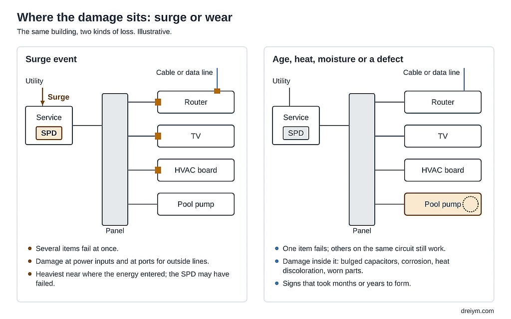
When lightning is put forward as the cause of damage, the evidence still has to support it. A strike tends to reach several circuits and devices at once, while a failure that starts inside one part usually stays there. Lightning detection records can show whether cloud-to-ground activity was recorded nearby, and we weigh them together with the physical evidence, not in place of it. See our lightning damage investigations and our lightning analyses in Charlotte.
What you receive
- A report with every reading, the method used for each and the site conditions at the time, so later tests can be compared with it
- Photographs of each connection, with defects marked
- A comparison with the carrier’s or owner’s specification where one applies, which is often stricter than the NEC®’s 25 ohms
- Recommended corrections in order of priority, from bonding and single point grounding to surge protection and changes to the ground system
- A report PE-stamped where required
Aerial documentation of tower tops and hard-to-reach structures is available through our drone services, and electrical equipment can be checked for heating with an infrared inspection on the same visit.
Frequently asked questions
Do cell towers attract lightning?
Not because they are metal. The National Weather Service names height, a pointed shape and isolation as the main factors in where lightning strikes, and says the presence of metal makes no difference. A tall, isolated tower is struck often for the same reason a lone tree on a hill is.
What standards cover telecom grounding?
ANSI®/TIA-607 is the telecommunications standard for bonding and grounding, with installation practice in ANSI®/NECA/BICSI-607. NFPA® 780 covers lightning protection systems, and IEEE® 81 is the guide for measuring earth resistivity and the resistance of a grounding system.
How is a tower’s ground system tested?
With fall-of-potential tests of the ground ring and electrodes where the site allows, clamp-on readings on grounds in service, continuity checks between the main ground bar and every bonded item, and soil resistivity tests where a ground is being designed or extended.
Can surge protection stop lightning damage?
It is one part of the answer. At the Hill Country tower site, our report recommended surge protection on the power feed and at both ends of every copper cable that runs outdoors or underground, together with bonding changes and a single point ground for the sensitive equipment.
What is a single point ground?
An arrangement in which sensitive equipment, its racks and its cable trays are bonded to one ground bar, with one path back to the buried ground system. It was one of our recommendations at the Hill Country tower site, where equipment racks were anchored into a slab whose rebar had no connection we could find to the ground system.
Talk to an engineer
Have a site that keeps getting hit, or a lightning claim to evaluate? Request a free quote. We typically respond within one business day.

Get your project started
We typically respond within one business day.