Corrosion and Cathodic Protection
Cathodic Protection in High-Resistivity Rocky Mountain Soils
CP in high-resistivity Rocky Mountain soil takes more voltage to push the same current, so we survey the whole route and size for the driest season.
Contents
Dry, rocky ground is hard on cathodic protection (CP). It resists the current the system runs on, and much of the Rocky Mountain region is like that. High-resistivity soil changes a cathodic protection design from the first survey to the size of the rectifier.
Key takeaways
- Dry, rocky ground resists the current a cathodic protection system runs on, and much of the Rocky Mountain region is like that.
- Anode-to-earth resistance rises in step with soil resistivity, so in ground that reads ten times higher the same anodes need about ten times the voltage.
- Galvanic anodes have little driving voltage to spare: less than a volt for high-potential magnesium and about a quarter of a volt for zinc.
- Resistivity changes with the season, and once the soil water freezes it can climb past ten times the summer reading.
- Good design starts by measuring resistivity along the actual route, not with one reading at the rectifier site.
Project example: Water Line Soil Study, CP Design and Commissioning, McKinney
Why high resistivity makes cathodic protection harder
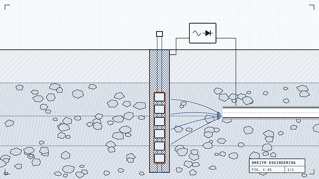
A CP system pushes DC current from its anodes, through the soil and onto the steel. So the soil is part of the circuit. Anode-to-earth resistance rises in step with soil resistivity. In ground that reads ten times higher, the same anodes need about ten times the voltage to deliver the same current. Wet Gulf Coast clay carries current easily, and a design copied from a job there can come up well short in a Colorado trench.
Galvanic anodes have little voltage to spare. High-potential magnesium has less than a volt of driving voltage against protected steel, and zinc has about a quarter of a volt. Unless the structure is small and well coated, cathodic protection in high-resistivity soil usually means impressed current, with a rectifier supplying the voltage.
A field example from our work: Soil Corrosivity Memo for a New Industrial Gas Plant, Taylor
If the design assumed better ground than the site has, that rectifier hits its voltage limit below the design current. The sections farthest from the groundbed lose protection first.
What Rocky Mountain soils do differently
In the foothills and mountains, crews hit decomposed granite, cobble and shallow bedrock, with pockets of finer soil in between. Out on the plains, DJ Basin gathering lines see less rock, but resistivity still swings from stretch to stretch. Readings can change by a factor of ten between test locations a few hundred feet apart.
The season matters too. A survey in a wet spring can read a fraction of what the same ground reads in a dry September. Frozen ground is worse still. Once the soil water freezes, resistivity can climb past ten times the summer reading. That matters most for shallow anodes and for surveys done in winter. The active part of a deep groundbed sits well below the frost line.
For a field example, see the energy-sector CP work in North Dakota.
Designing for high-resistivity soil
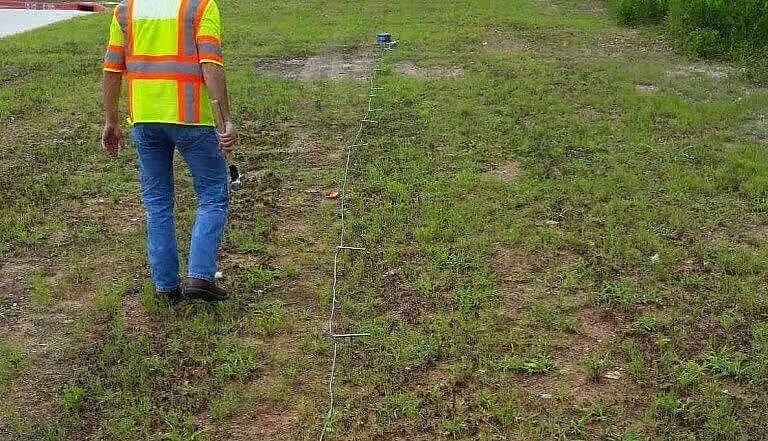
We start by measuring along the actual route, not with one reading at the rectifier site. A proper soil resistivity and corrosivity survey takes readings at several pin spacings. That shows how the ground changes with depth as well as distance, and most of the design follows from it.
When the surface is dry rock and better ground lies deeper, deep groundbed systems are often the answer. The anodes go down a drilled hole, at least 50 feet and often a few hundred, into wetter, lower-resistivity layers. Nearby water wells give a cheap first look at what is down there. Colorado’s Division of Water Resources has a public well permit search with well depths and static water levels.
If drilling won’t reach better ground, say solid rock with no water in reach, we spread the anodes out instead. Many anodes along the structure add up to a lot of anode length. Total length is what brings groundbed resistance down.
Then we size the rectifier and groundbed for the driest reading we expect. We leave room for groundbed resistance to creep up over the years. The design is stamped by a licensed PE through our cathodic protection design practice.
What owners should check
If you own buried steel in this kind of ground, ask what resistivity the design assumed and when it was measured.
High resistivity also makes routine surveys harder to read. With the current on, part of every pipe-to-soil reading is voltage drop through the soil. The drier the ground, the bigger that error. For gas pipelines, federal rules say that drop has to be considered when judging protection (49 CFR Part 192, Appendix D). In practice that usually means interrupting the rectifiers and reading instant-off potentials.
The same questions apply to Colorado UST owners on the state’s 3-year testing cycle. Our Colorado UST cathodic protection program covers testing and PE-stamped design in one engagement. Our Colorado team is based in Westcliffe.