Electrical Interactive
4-20 mA Current Loop: How It Works, With a Live Simulator
How a 4-20 mA current loop works: live zero, the 250 ohm resistor, loop resistance, NAMUR NE 43 faults and the current mirror inside a transmitter.

Contents
- How a 4-20 mA current loop works
- 4-20 mA calculator
- Try a 4-20 mA current loop in our simulator
- How a 4-20 mA transmitter works as a current mirror with a gain of 100
- What limits the accuracy of a current mirror
- Why current beats voltage over long wires
- Loop resistance and compliance voltage
- What 3.6 mA and 21 mA mean under NAMUR NE 43
- Two-wire, three-wire and four-wire transmitters
- Troubleshooting a 4-20 mA current loop
- When a 4-20 mA loop becomes evidence
- Frequently asked questions
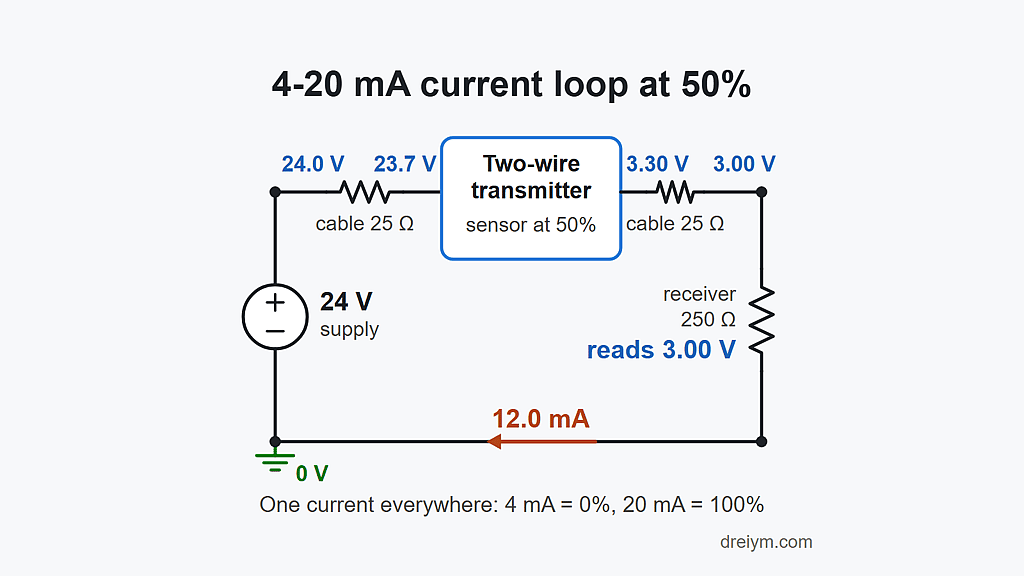
A 4-20 mA current loop sends one measurement as a DC current. At 0% of the instrument’s range the current is 4 mA, and at 100% it’s 20 mA. It flows in series through a 24 V supply, a transmitter out in the field, the cable and a receiver in the control room. At the receiver, a 250 ohm resistor turns it into 1 to 5 V. Because it’s the same current everywhere in the loop, long wires don’t change the reading.
Key takeaways
- A 4-20 mA current loop sends one measurement as a DC current: 4 mA at 0% of the range and 20 mA at 100%.
- The current flows in series through a 24 V supply, a field transmitter, the cable and a receiver in the control room.
- The zero is a live zero of 4 mA, partly because a two-wire transmitter runs its electronics on part of the loop current.
- With a 250 ohm resistor, 4 mA reads as 1 V and 20 mA as 5 V, the standard 1 to 5 V range.
Skip ahead to the calculator, the live simulator, compliance voltage, NAMUR NE 43 fault currents or troubleshooting.
How a 4-20 mA current loop works
A two-wire loop has four parts, all in series:
- The loop supply, usually 24 V DC. It’s often built into the control system’s input card.
- The transmitter at the sensor, which measures a pressure, level, flow or temperature and sets the loop current to match. It’s powered from the same two wires.
- The cable, usually a twisted, shielded pair that often runs for hundreds of meters.
- The receiver, a PLC or DCS input that reads the current as the voltage across a 250 Ω resistor.
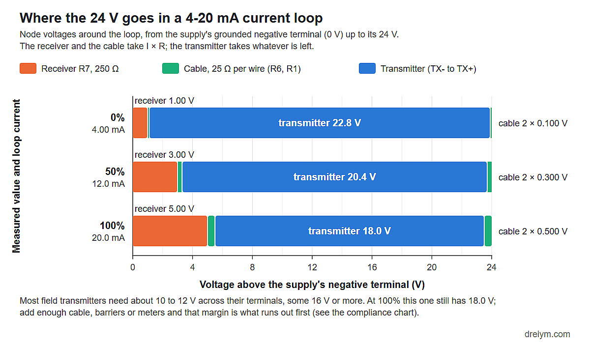
A transmitter doesn’t send a voltage. It’s a regulator that passes exactly the right current, however much the cable and the receiver drop. At full scale in our simulator, the receiver takes 5.00 V and each 25 Ω cable wire takes 0.500 V. That leaves 18.0 V for the transmitter.
Why the zero is 4 mA instead of 0
A zero that still carries current is called a live zero, and there are two reasons for it. The first is power. A two-wire transmitter runs its electronics on part of the loop current, so it needs some current even at 0%. A transmitter IC such as TI’s XTR115 draws about 200 µA by itself.
The second is that you can tell a true zero from a dead loop. A broken wire, a blown fuse or a failed supply gives 0 mA, and no valid measurement ever does. The idea goes back to the 3 to 15 psi pneumatic signal, as Fluke®’s history of the current loop explains.
Reading the loop as 1 to 5 V with a 250 ohm resistor
Most receivers measure the current as a voltage across a precision resistor. With a 250 ohm resistor, 4 mA gives 1 V and 20 mA gives 5 V. That’s the standard 1 to 5 V range. The measured value is then % of span = (I − 4 mA) ÷ 16 mA × 100. So a 0 to 150 psi transmitter sending 12.8 mA is reading 55%, or 82.5 psi.
| Measured value | Loop current | Voltage across 250 Ω |
|---|---|---|
| 0% | 4.00 mA | 1.00 V |
| 25% | 8.00 mA | 2.00 V |
| 50% | 12.0 mA | 3.00 V |
| 75% | 16.0 mA | 4.00 V |
| 100% | 20.0 mA | 5.00 V |
Any tolerance on that resistor becomes a gain error on every reading, so input cards use precision parts. HART® instruments put a digital signal on top of the current. They need at least about 250 Ω in the loop.
Calculation record: 4-20 mA loop calculator
Dreiym Engineering. Method and edition: Linear 4-20 mA scaling, with NAMUR NE 43 signal levels.
Printed . Inputs and results as entered on https://www.dreiym.com/2026/10/03/4-20-ma-current-loop/
Screening estimate, not an engineering study.
4-20 mA calculator
Convert a 4-20 mA signal to the process value it stands for, or a value to the current, and check that the loop has enough voltage for the transmitter. Pick a quick start or enter your own loop; the answer updates as you type.
The calculator needs JavaScript®. The formulas it uses are under "How the calculation works" below.
Quick start Fills in the form. Change anything after.
Result
In range, and the loop has enough voltage
12.00 mA is 75 psi (50.0% of span), 3.000 V across the 250 Ω receiver. The loop has enough voltage: the transmitter gets 18.48 V at 21 mA and needs 12 V.
- Process value
- 75 psi
- Loop current
- 12.00 mA
- Percent of span
- 50.0%
- At the transmitter, 21 mA (needs 12 V)
- 18.48 V
What can I do?
Check the transmitter, barrier and input card data sheets before you change the loop.
Screening estimate for an ideal loop. Check the transmitter, barrier and input card data sheets before you rely on it. Ask an engineer or see our electrical engineering services.
Full results and steps
| Process value | 75 psi |
|---|---|
| Loop current | 12.00 mA |
| Percent of span | 50.0% |
| Voltage across the receiver | 3.000 V |
| Loop resistance | 262.8 Ω (receiver 250, wire 12.8, other 0) |
| Voltage at the transmitter, 20 mA | 18.74 V |
| Voltage at the transmitter, 21 mA | 18.48 V |
| Maximum loop resistance at 21 mA | 571 Ω |
| Longest one-way run, 18 AWG copper | 25,171 ft |
- Span: 150 − 0 = 150 psi.
- Percent of span = (12.00 − 4) ÷ 16 × 100 = 50.00%. Process value = 0 + 150 × 50.00% = 75.
- Receiver voltage = 12.00 mA × 250 Ω = 3.000 V.
- Wire resistance = 2 × 1,000 ft × 6.385 Ω per 1,000 ft = 12.77 Ω. Loop resistance = 250 + 12.77 + 0 = 262.8 Ω.
- At 20 mA: 24 − 0.020 × 262.8 = 18.74 V. At 21 mA: 24 − 0.021 × 262.8 = 18.48 V. The transmitter needs 12 V.
- Maximum loop resistance = (24 − 12) ÷ 0.021 = 571 Ω, leaving 321 Ω for wire: 25,171 ft one way.
Instrument loop that won't read right, or a failure to explain?
Dreiym's licensed Professional Engineers review control and instrument circuits, and our forensic engineers investigate electrical failures and the losses that follow, PE-stamped where required. Free quote; we typically respond within one business day.
Safety and limits
Hazardous locations: Intrinsically safe loops must follow the barrier and instrument entity parameters and the control drawing. This calculator does not check them.
Screening tool: Screening estimate for education and planning. Not an engineering study or a design, and not a substitute for a licensed engineer's review where one is required.
How the calculation works
- Percent of span = (I − 4 mA) ÷ 16 mA × 100. Process value = LRV + (URV − LRV) × percent ÷ 100. Going the other way, I = 4 mA + 16 mA × (PV − LRV) ÷ (URV − LRV). A reversed range (URV below LRV) works the same way.
- Receiver voltage = I × R. With 250 Ω, 4 to 20 mA reads as 1 to 5 V.
- Loop resistance = receiver resistor + other series resistance + 2 × one-way length × wire resistance per foot (out and back).
- Voltage left for the transmitter = supply voltage − I × loop resistance, checked at 20 mA and at 21 mA, the lowest NAMUR NE 43 high-fault current.
- Maximum loop resistance = (supply voltage − transmitter minimum voltage) ÷ 0.021 A. The longest cable run is what remains after the fixed resistances, divided by twice the wire resistance per foot.
- Suggestions when the loop is short of voltage: the supply that keeps the minimum voltage at 21 mA is the minimum voltage + 0.021 A × loop resistance; the wire suggestion is the thinnest size in the list that does the same on this run.
- Wire resistance is for solid annealed copper at 20 °C (ohms per 1,000 ft: 24 AWG 25.67, 22 AWG 16.14, 20 AWG 10.15, 18 AWG 6.385, 16 AWG 4.016, 14 AWG 2.525, 12 AWG 1.588). Stranded and warmer conductors run a few percent higher; copper resistance rises about 0.39% per °C.
NAMUR NE 43 signal ranges
| Current | Meaning |
|---|---|
| 3.6 mA or less | Failure signal (low) |
| 3.6 to 3.8 mA | Outside the measurement range; not used for measurement or failure |
| 3.8 to 4.0 mA | Measurement, below range (under-range) |
| 4.0 to 20.0 mA | Measurement, 0 to 100% of span |
| 20.0 to 20.5 mA | Measurement, above range (over-range) |
| 20.5 to 21.0 mA | Outside the measurement range; not used for measurement or failure |
| 21.0 mA or more | Failure signal (high) |
Sources
Sources: NAMUR NE 43, Standardization of the signal level for the failure information of digital transmitters; ISA-50.00.01 (analog 4-20 mA signal compatibility); copper conductor resistance from the standard AWG table for annealed copper at 20 °C (ASTM® B258 diameters, 100% IACS); temperature coefficient of copper 0.00393 per °C.
Cite or share this tool
Dreiym Engineering. 4-20 mA loop calculator. Method: 4-20 mA scaling with NAMUR NE 43 signal levels. https://www.dreiym.com/2026/10/03/4-20-ma-current-loop/
Instructors and shops are welcome to link to this tool or put its address on a handout. It is free, needs no sign-up and works on a phone.
Link copied.Citation copied.The copy did not work. The text is selected, so copy it with your device.AccessedVerified against published cases
We ran these worked examples through this calculator. Source: Tony R. Kuphaldt, Analog Instrumentation Circuits, Modular Electronics Learning (ModEL) project, last update May 10, 2026, Chapter 2 example calculations (Creative Commons Attribution 4.0). Free copy (PDF)
| Case | Published | This calculator |
|---|---|---|
| 34.7% of span, as a current | 9.552 mA | 9.552 mA |
| 8.55 mA to a control valve (4 mA shut, 20 mA wide open): how far open | 28.4% | 28.44% |
| Flow transmitter ranged 0 to 350 GPM, at 204 GPM | 13.33 mA | 13.33 mA |
| Temperature transmitter ranged 50 to 140 °F, at 79 °F | 9.16 mA | 9.16 mA |
Ranges entered as in the source: 0 to 100% for the first two rows.
Method and edition: Linear 4-20 mA scaling, with NAMUR NE 43 signal levels.
Changes
- November 19, 2026: Published test cases and a printable calculation record added.
Worked example: a pressure transmitter loop
The “Pressure transmitter” quick start is a 0 to 150 psi transmitter sending 12.00 mA over 1,000 ft of 18 AWG copper pair, with a 24 V supply, a 250 Ω receiver and a transmitter that needs at least 12 V.
- Reading: (12.00 − 4) ÷ 16 × 100 = 50.0% of span, so the pressure is 75 psi, and the receiver sees 12.00 mA × 250 Ω = 3.000 V.
- Wire: 2 × 1,000 ft × 6.385 Ω per 1,000 ft = 12.77 Ω, so the loop resistance is 250 + 12.77 = 262.8 Ω.
- Voltage check: at 21 mA, the lowest NAMUR NE 43 high fault current, the transmitter gets 24 − 0.021 × 262.8 = 18.48 V, more than the 12 V it needs.
- Margin: the loop can have up to (24 − 12) ÷ 0.021 = 571 Ω, which leaves 321 Ω for wire, or about 25,000 ft one way of 18 AWG.
Related service
Studies modeled in ETAP® and SKM, field testing and electrical design by licensed PEs.
Try a 4-20 mA current loop in our simulator
The simulator below opens on a complete two-wire loop at 50%. The 24 V supply, V1, is on the left, and the 250 Ω receiver, R7, is on the right. R1 and R6 are the cable, 25 Ω each, or about 1.2 km of 18 AWG pair. The sensor V2 reads 2.5 V of its 0 to 5 V range. That puts 12.0 mA through the loop, and R7 reads 3.00 V. Double-click V2 to enter a different value, or double-click SW1 to break the wire. The same loop is also set up at 0%, at 100% and with a broken wire. It’s an educational model with ideal parts. There are more examples in our online circuit simulator.
How a 4-20 mA transmitter works as a current mirror with a gain of 100
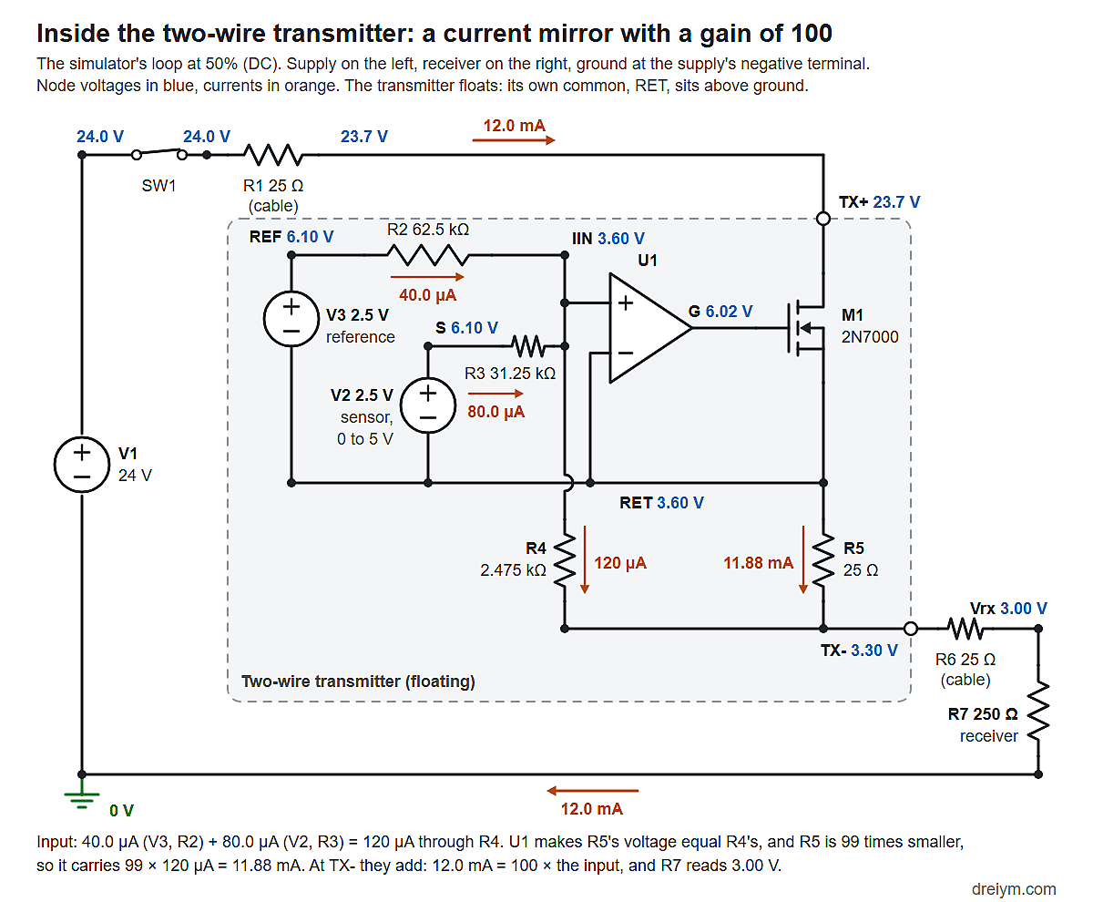
Electrically, a two-wire 4-20 mA transmitter is a precision current regulator. Ours works like TI’s XTR115 IC, with a 2.5 V reference and resistors of 2.475 kΩ and 25 Ω.
Start at the input. The sensor V2 (0 to 5 V) drives 0 to 160 µA through R3 (31.25 kΩ). The 2.5 V reference V3 adds a fixed 40 µA through R2 (62.5 kΩ). That fixed current is the live zero. Both currents flow into node IIN, which the op-amp U1 holds at the transmitter’s own common, RET. At 50% the total is 40 + 80 = 120 µA.
Then comes the mirror. The 120 µA carries on through R4 (2.475 kΩ, shown as 2.48 kΩ) to the negative terminal, TX-. U1 drives the MOSFET M1 until R5 (25 Ω) has the same voltage across it as R4. Since R5 is 99 times smaller, it carries 99 times the current, or 11.88 mA. The two currents meet at TX- and add up to 12.0 mA, exactly 100 times the input.
The pass transistor, M1, drops whatever voltage the loop leaves. At 100% it has 17.5 V across it and dissipates 0.350 W, or 88% of the 2N7000’s 0.4 W rating. The XTR115 drives an external NPN transistor, but our simulator uses a MOSFET, whose gate draws no current.
What limits the accuracy of a current mirror
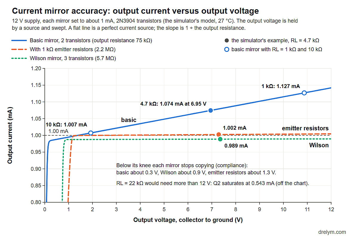
The classic transistor current mirror shows why a transmitter uses an op-amp instead. In our current mirror example, 12 V and R1 (11.3 kΩ) set 1.003 mA in Q1, a diode-connected 2N3904. Q2 copies that current into a 4.7 kΩ load. The copy isn’t perfect, for three reasons:
- The transistors have finite beta. Both base currents come out of the reference, so the copy runs short by about 2/β. With the 2N3904’s β of 160, that’s about 1.2%.
- The Early effect makes collector current rise with collector voltage. Q1 sits at 0.67 V but Q2 is at 6.95 V, so Q2 delivers 1.074 mA, 7% more than it should. With a 1 kΩ load it delivers 1.127 mA, and with 10 kΩ it’s 1.007 mA. The copy moves 12% with the load because its output resistance is only about 75 kΩ.
- Then there’s compliance. A 22 kΩ load needs more voltage than the 12 V supply can give, so Q2 saturates at only 0.543 mA.
Better copies with emitter resistors and the Wilson mirror
With emitter resistors of 1 kΩ, the voltage drops across them set the ratio, not the transistors. Over the same 1 kΩ to 10 kΩ loads, the output moves only 0.4%. The output resistance rises about 30 times, to 2.2 MΩ, at a cost of about 1 V of compliance.
The Wilson mirror adds a third transistor and negative feedback. That brings the base-current error down to about 2/β², which is under 0.01%. Its output resistance is 5.7 MΩ, so over the same loads it moves just 0.16%. The output still sits 0.8% below the reference current, though. That’s the Early effect again, and the improved Wilson mirror removes it with a fourth transistor.
A precision transmitter sets its ratio with two resistors instead (R4 ÷ R5 = 99). The op-amp’s gain holds that ratio no matter what voltage is across the transistor. At full scale in our loop, adding 475 Ω of cable doesn’t change the first six digits of the current. For the full derivation of these errors, see the Analog Devices chapter on the current mirror.
Why current beats voltage over long wires
A voltage signal picks up every drop along a wire that carries current. It also picks up any difference between the grounds at the two ends. In a series loop, the receiver sees the current the transmitter sets, as long as the transmitter has voltage to spare. In the simulator, the 50 Ω of cable drops 0.6 V at 12 mA, and R7 still reads 3.00 V.
In power circuits, where the drop over a long run matters to the load, our voltage drop calculator works it out for copper and aluminum wire.
Noise is less of a problem in a 4-20 mA current loop, too. The low-impedance receiver turns stray induced currents into only small voltages. The same two wires carry power and signal, and a cut wire reads 0 mA, not a believable wrong value. There’s more on electrical noise in our article on the top causes of PLC control system failure.
Loop resistance and compliance voltage
A transmitter can only hold its current while it has its minimum operating voltage. For most field instruments that’s about 10 to 12 V, and some need 16 V or more. A bare XTR115 needs 7.5 V. The rest of the supply is the loop’s compliance voltage, and everything else in the loop shares it. So the largest loop resistance is:
Rmax = (Vsupply − Vtransmitter, min) ÷ Imax.
For a 24 V supply and a 12 V transmitter, Rmax = 12 V ÷ 20 mA = 600 Ω. If an upscale NE 43 alarm at 22 mA also has to get through, the limit is 545 Ω. Take away the 250 Ω receiver and you’re left with 295 Ω for the cable, barriers, displays and HART® resistors.
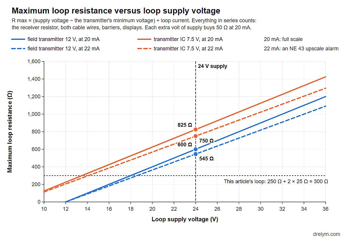
Go past that limit and the loop fails without warning. In the loop at 100%, change R1 to 1 kΩ. Only 18.5 mA flows and R7 reads 4.61 V, or 90%, while the sensor still reads 100%. U1 sits at its +15 V limit, but nothing tells the control system. The error only shows up near the top of the range, right where high-level alarms need an accurate reading. Our ideal transmitter keeps regulating below 1 V. A real one fails far sooner.
What 3.6 mA and 21 mA mean under NAMUR NE 43
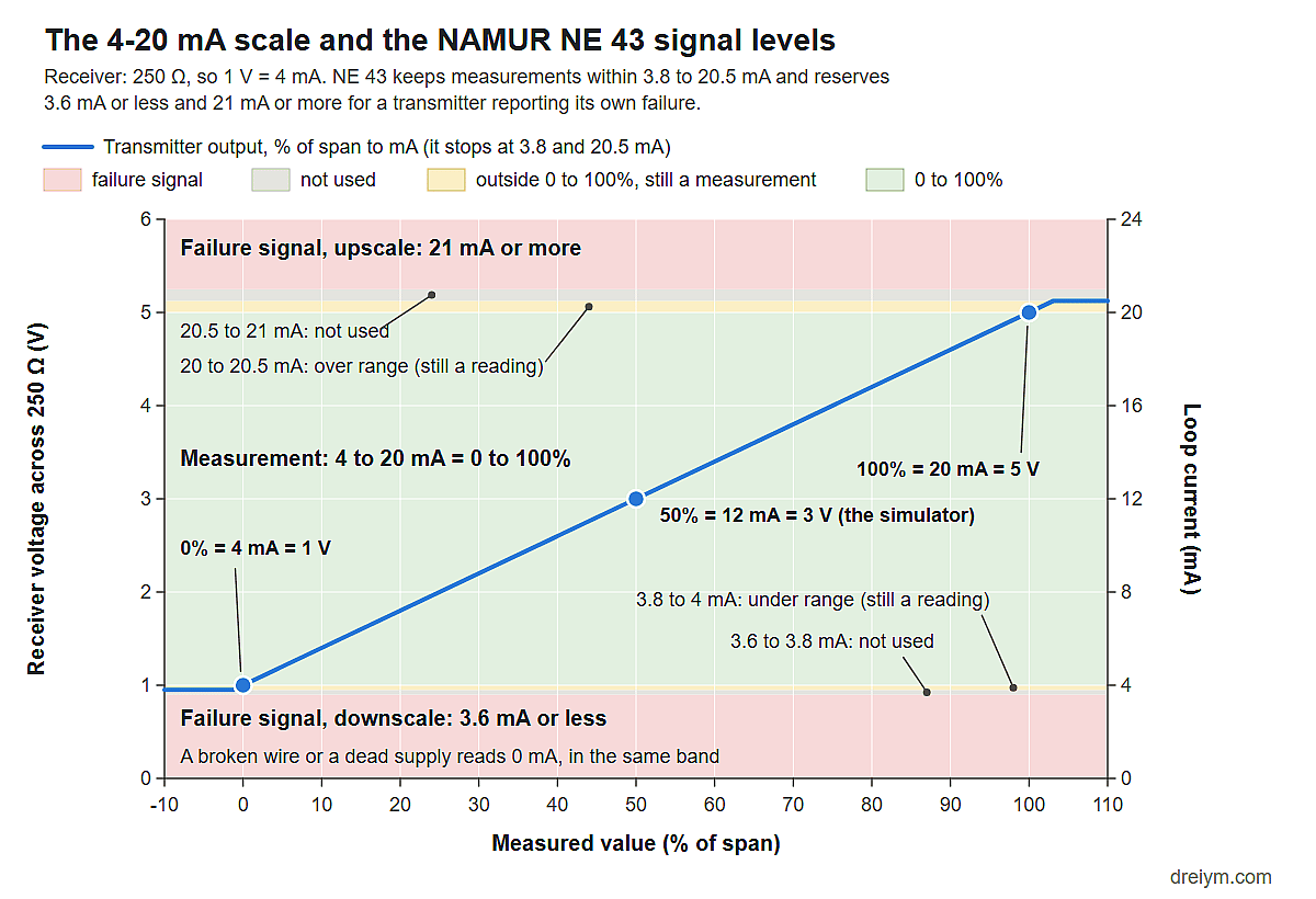
NAMUR Recommendation NE 43 standardizes the signal levels a transmitter uses to tell the control system it has failed:
| Loop current | Meaning under NE 43 |
|---|---|
| 3.6 mA or less | Failure signal, downscale |
| 3.6 to 3.8 mA | Not used |
| 3.8 to 4.0 mA | Below range, still a reading |
| 4.0 to 20.0 mA | Measurement, 0 to 100% |
| 20.0 to 20.5 mA | Above range, still a reading |
| 20.5 to 21.0 mA | Not used |
| 21.0 mA or more | Failure signal, upscale |
An NE 43 transmitter keeps its readings between 3.8 and 20.5 mA, so no real reading can look like a failure. Whether it fails downscale or upscale is a setting. Which one is safer depends on what the loop protects, so document the choice. Check the settings on each transmitter, since not all of them use the NE 43 levels. The input card also has to be scaled to read outside 4 to 20 mA. If it clips at 20 mA, a 21 mA failure signal looks like an ordinary 100% reading.
A broken wire or a dead supply reads 0 mA. That’s in the low failure band, so an NE 43 receiver alarms on it too. A short across the transmitter drives the current far above 21 mA. In the simulator, if you set V2 to 5.5 V, the loop carries 21.6 mA. An NE 43 receiver would call that a failure, although a real NE 43 transmitter would stop at 20.5 mA.
Two-wire, three-wire and four-wire transmitters
ANSI®/ISA-50.00.01, the standard for 4-20 mA signals, groups transmitters by how many wires they use. A two-wire transmitter uses one pair for both power and signal, so it has to live on less than 4 mA. Three-wire transmitters add a supply wire, and four-wire transmitters have a separate power supply, often at line voltage.
An input card is either active, supplying the loop voltage itself, or passive, expecting power from somewhere else. Wiring two supplies into a loop, or none, is a common commissioning mistake. A loop should also be grounded at one point only. If both the transmitter output and the receiver input are grounded, some current returns through the ground instead of the receiver. An isolator fixes that.
Troubleshooting a 4-20 mA current loop
Where you can, measure without opening the loop. Read the voltage across the 250 Ω resistor (3.00 V ÷ 250 Ω = 12.0 mA), or use the transmitter’s test terminals or a clamp meter. Opening a running loop sends the control system 0 mA, and that can move a valve or trip an interlock. If you have to open it for a meter in series, clear it with operations first. Put the loop in manual or bypass before you open it. Then compare the current with the bands above.
- No current at all (0 mA) means an open loop or no supply. Look for a broken wire, a loose terminal or a blown fuse.
- At or below 3.6 mA, or at or above 21 mA (or the transmitter’s own alarm levels), the transmitter is reporting a failure. Read its diagnostics.
- A reading stuck near 3.8 or 20.5 mA (or the transmitter’s own saturation levels) means the process is outside the transmitter’s range, or the range is set wrong.
- Readings that top out below 20 mA mean there isn’t enough loop voltage. Check the supply, the loop resistance and anything that’s been added in series.
- A noisy or drifting reading can come from a second ground point, a shield grounded at both ends, or a corroded terminal.
In hazardous (classified) areas, work on a loop only under the plant’s procedures. For the control-system side, see our guide to HMI and PLC troubleshooting.
When a 4-20 mA loop becomes evidence
After a process upset, a fire or an equipment failure, the questions often come down to what a loop reported and when. Did the transmitter send a failure signal, and did the control system treat it as one? Was the loop short of voltage at the top of its range? Was the fault mode set upscale or downscale, and why?
To answer them, we reconstruct the loop as it was. That means its configuration and fault mode, wiring and voltage budget, input scaling, alarm limits and historian record. Before anything is reset, replaced or recalibrated, preserve the transmitter, its configuration and the control system’s logs.
Our electrical failure analysis engineers investigate failed electrical and control equipment for attorneys, insurers and adjusters. Our industrial fire investigations cover plants and facilities. To bring us in on a loss, submit a forensic assignment or request an expert CV and rate schedule.
Frequently asked questions
Why is 4-20 mA used instead of 0-20 mA?
The 4 mA zero is what powers a two-wire transmitter’s electronics. It also lets the receiver tell a true zero (4 mA) from a broken wire or a dead supply (0 mA). A 0-20 mA signal can’t do either.
What does a 250 ohm resistor do in a 4-20 mA loop?
It turns the current into a voltage the input can measure, so 4 to 20 mA becomes 1 to 5 V.
How far can a 4-20 mA signal travel?
The limit comes from loop resistance, not distance as such. With 24 V, a 12 V transmitter and a 250 Ω receiver, you have 350 Ω left at 20 mA. That’s 175 Ω per wire, or about 8 km of 18 AWG copper before any margin. In practice, noise, barriers and plant standards usually keep runs shorter than that.
Should I use 4-20 mA or 0-10 V?
For short runs inside one panel, 0-10 V is simple and cheap. Use 4-20 mA for long runs, noisy plants and two-wire field instruments, or anywhere you need to detect a broken wire.
Standards cited: ANSI®/ISA-50.00.01-1975 (R2012) and NAMUR NE 43. The simulator’s numbers come from its own device models (2N3904, 2N7000 and an ideal op-amp) at 27 °C.