Proven Arc Flash Labeling: What You Need To Know
Arc flash labeling under NFPA 70E: what labels must show, how incident energy is calculated under IEEE 1584, and when to update your study.
Contents
- What is an arc flash?
- How hot can an arc flash get?
- What is the blast force of an arc flash?
- What is the risk to a human from an arc flash?
- What are calorie limits and why are they important?
- Arc Flash Labeling: How to Label Electrical Equipment
- How to Calculate Arc Flash Hazards?
- What if an arc flash injury has already occurred?
What is an arc flash?
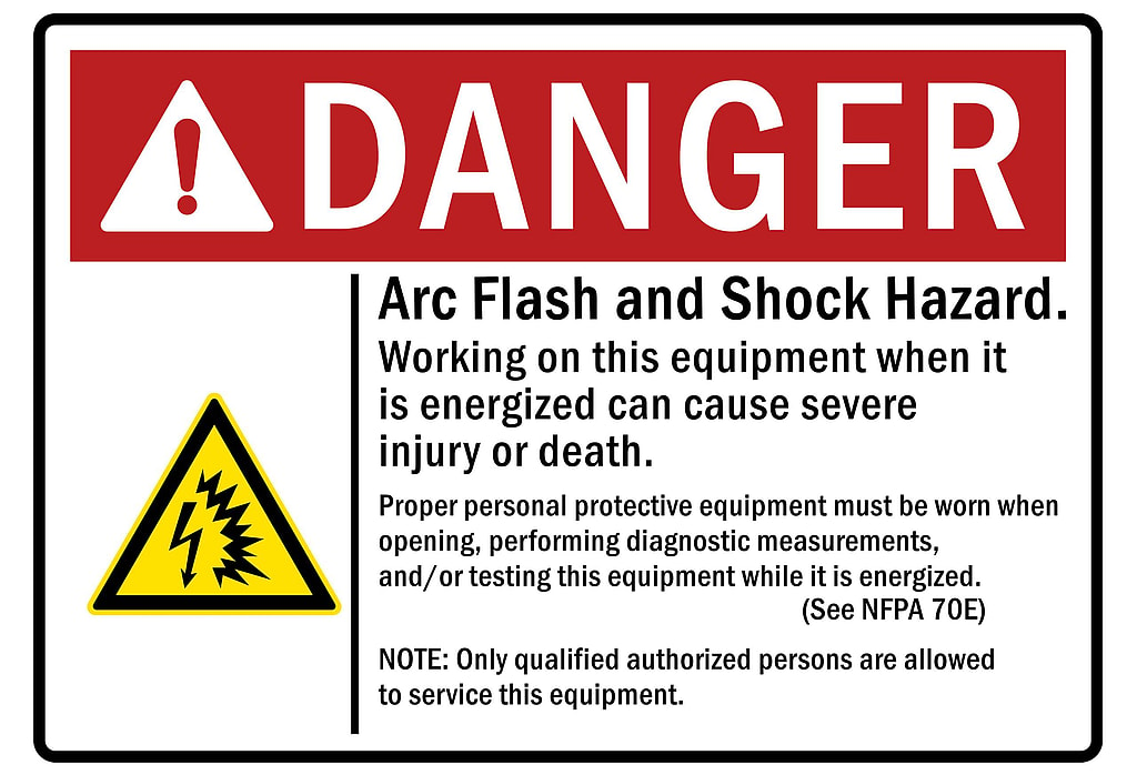
An arc flash is a sudden release of electrical energy. It occurs when a fault or short circuit causes an arc between two conductors or a conductor and a ground. An arc flash can generate intense heat, light, sound, and pressure that can harm anyone nearby. Arc flash labeling warns workers of that hazard before they open the equipment.
Related project: Community Campus Arc Flash Study and IR Scan, Austin
How hot can an arc flash get?
An arc flash can reach temperatures of up to 35,000 degrees Fahrenheit. That is hotter than the surface of the sun. This extreme heat can ignite clothing, melt metal, and cause severe burns to the skin and eyes.
Arc flash heat can pose a serious risk to a person, even without direct exposure to the arc. The radiant heat can cause second- or third-degree burns to any exposed skin within several feet of the arc. The heat can also ignite flammable materials, such as clothing, hair, or paper, and cause more severe injuries. The intense heat can also damage the respiratory system and cause inhalation injuries. This is more likely if smoke or toxic gases are present. Therefore, it is essential to wear appropriate personal protective equipment (PPE) and avoid working near energized electrical equipment whenever possible.
See how this worked on a real job: Terminal and Coastal Site Arc Flash Studies, Houston to Corpus Christi
What is the blast force of an arc flash?
An arc flash can also create a powerful blast wave. The wave can knock workers off their feet, hurl objects across the room, and damage equipment and structures. Neither NFPA 70E® nor IEEE 1584 gives a way to calculate arc blast pressure. No consensus method exists for it either. NFPA 70E also notes that its PPE requirements do not address injuries from the blast itself.
The most-cited estimate is Ralph Lee’s “Pressures Developed by Arcs” (IEEE Transactions on Industry Applications, 1987). It predicts an impulse of roughly 11.5 x I(kA) / d(ft)^0.9 in pounds per square foot. That is on the order of 150 to 300 lb/ft2, or about 1 to 2 psi, a few feet from a 25 to 40 kA arc. Spread over the chest and face, that is still several hundred pounds of force. That force is enough to throw a worker off a ladder. Closer to the arc, or at higher currents, the pressure climbs toward roughly 5 psi. Eardrums begin to rupture at about that pressure.
What is the risk to a human from an arc flash?
An arc flash can cause serious injuries and fatalities to exposed workers. The effects of an arc flash can include:
A field example from our work: Arc Flash Study at a Truss and Wall Panel Plant, Pflugerville
- Thermal burns: The intense heat from an arc flash can cause deep and painful burns that can damage the skin, muscles, nerves, and organs. Burns can also lead to infections, scarring, and disfigurement.
- Eye injuries: The bright light from an arc flash can cause temporary or permanent blindness, as well as damage to the retina, cornea, and lens. Eye injuries can also impair vision, cause sensitivity to light, and increase the risk of cataracts and glaucoma.
- Hearing loss: The loud noise from an arc flash can rupture the eardrums, damage the inner ear, and cause temporary or permanent hearing loss. Hearing loss can also affect balance, communication, and quality of life.
Breathing, Heart, and Other Effects
- Respiratory problems: The smoke and gases from an arc flash can irritate the lungs, throat, and nose, and cause coughing, wheezing, shortness of breath, and asthma. Some of the gases, such as carbon monoxide, can also be toxic and cause poisoning, brain damage, and death.
- Cardiac arrest: An electric shock, which can accompany an arc flash when the worker touches energized parts or is in the arc’s current path, can stop the heart, cause an irregular heartbeat, and damage the heart muscle. Cardiac arrest can also result in brain damage, coma, and death.
- Psychological trauma: The experience of an arc flash can cause post-traumatic stress disorder (PTSD), anxiety, depression, and flashbacks. Psychological trauma can also affect memory, concentration, sleep, and relationships.
- Lung collapse: Very close to a large arc, the pressure wave can compress the air in the lungs and cause them to rupture or collapse. It takes far more pressure to injure the lungs than to rupture eardrums, so this is rare. This condition is known as pneumothorax. Lung collapse can cause severe breathing difficulties, chest pain, low blood pressure, and cyanosis (bluish skin). Lung collapse can also be life-threatening and require emergency treatment with a chest tube or surgery.
What are calorie limits and why are they important?
In arc flash work, a calorie limit is a level of incident energy. Incident energy is the heat energy that reaches a surface at a given distance from the arc. Its unit is calories per square centimeter (cal/cm2). The one that matters most, 1.2 cal/cm2, is the incident energy at which a second-degree burn on bare skin is likely to begin. A second-degree burn damages the outer and inner layers of the skin, causing blisters, pain, and swelling.
Related project: Four-Area Plant Arc Flash Studies, Grapeland
Calorie limits are important because they answer two separate questions for each piece of equipment: how far from the arc a worker needs arc flash protection, and how much protection the worker needs inside that distance. The first is the arc flash boundary (older editions of NFPA 70E called it the flash protection boundary). The second is the arc rating of the clothing and PPE.
How Distance Sets the Arc Flash Boundary
Incident energy falls off rapidly with distance from the arc source. The arc flash boundary is simply the distance at which the incident energy has dropped to 1.2 cal/cm2. The more energy an arc at a given piece of equipment can deliver, the farther out that boundary extends. More energy also means a higher required arc rating for anyone working inside it.
For a screening number at one piece of equipment, our arc flash calculator estimates the incident energy and the arc flash boundary with the IEEE 1584-2018 model. A label still needs the values from a full study.
The 1.2 cal/cm2 limit comes from the National Fire Protection Association (NFPA) 70E standard for electrical safety in the workplace, which defines the arc flash boundary as the distance at which the incident energy is 1.2 cal/cm2. Where an arc flash hazard exists, 130.5(G) and Table 130.5(G) require that the arc-rated clothing and PPE system selected have an arc rating equal to or greater than the available incident energy at the worker’s working distance, so equipment with 20 cal/cm2 of available incident energy requires at least a 20 cal/cm2 system, not 1.2 cal/cm2.
Arc Flash Labeling: How to Label Electrical Equipment
Labeling electrical equipment with information about the arc flash hazard and the required level of protection is one of the simplest ways to reduce arc flash injuries, though the safest choice is still to de-energize the equipment and establish an electrically safe work condition before working on it. Labeling electrical equipment can help workers identify the potential risks, follow the safe work practices, and wear the appropriate PPE.
NFPA 70E sets the arc flash labeling requirements in 130.5(H). The label must include all of the following:
- Nominal system voltage
- Arc flash boundary
- At least one of the following:
- The available incident energy and the corresponding working distance, or the arc flash PPE category for the equipment, but not both
- The minimum arc rating of clothing
- The site-specific level of PPE

Interactive explainer: select a bus in a sample arc flash study to see its label.
Arc Flash Sticker or Arc Flash Label?
An arc flash sticker and an arc flash label are the same thing. What matters is what it says and where the numbers came from. The values must come from a current arc flash risk assessment or study for that equipment, and the label must be updated when a change makes the information inaccurate. Labels are usually made in the ANSI Z535.4 safety sign format, with a signal word, and printed on durable material that stays legible where the equipment is installed.
Where Arc Flash Labeling Values Come From
The values on the label come from the arc flash risk assessment NFPA 70E requires, made either by an incident energy analysis (an arc flash study, usually to IEEE 1584) or by the arc flash PPE category method, never both on the same equipment. The study software can print labels from its results. A screening calculator or a rule of thumb cannot stand in for that assessment. NFPA 70E also does not permit using an incident energy result to pick a PPE category. The method and the data behind each label need documentation. Arc flash labels can also be customized with additional information, such as date, location, and warning signs.
NFPA 70E requires the label on electrical equipment, other than in dwelling units, that is likely to require examination, adjustment, servicing, or maintenance while energized, such as switchboards, panelboards, industrial control panels, meter socket enclosures, and motor control centers. The equipment owner is responsible for documenting, installing, and maintaining the label. NFPA 70E requires a review of the data behind it at intervals of no more than 5 years. It also requires an updated label whenever a change makes it inaccurate. Labels should be clearly visible and durable.
How to Calculate Arc Flash Hazards?
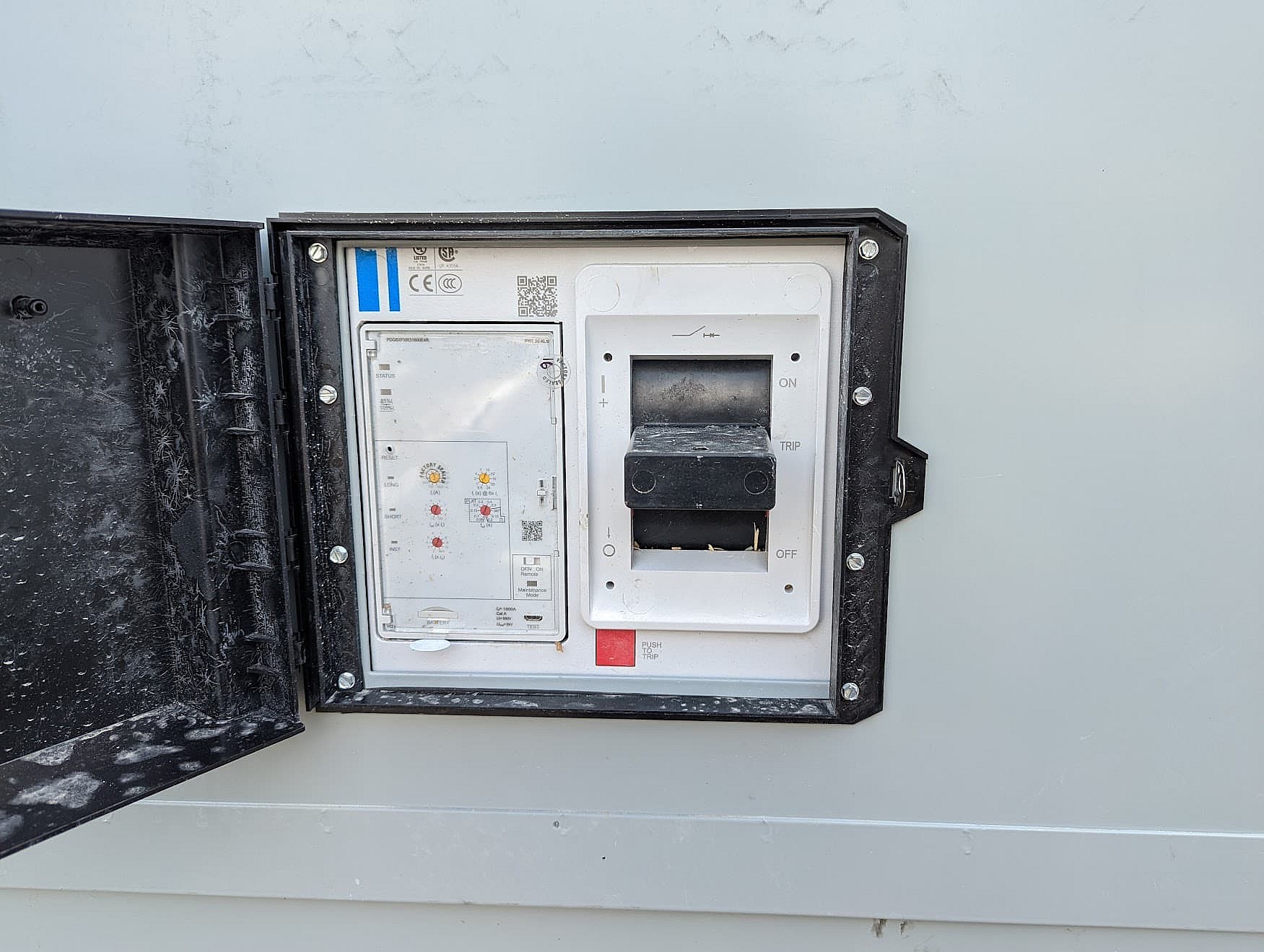
To perform an engineering calculation using ETAP® or SKM, an engineer needs to collect the following information in the field:
The type, model, and rating of the electrical equipment and the circuit breakers
The length, size, and material of the conductors
The type and location of the transformers and their impedance values
The source voltage and fault current at the service entrance
The load characteristics and power factor of the connected devices
Using this information, the software can model the electrical system. It then calculates the incident energy at the working distance and the arc flash boundary for each piece of equipment. The software can also generate arc flash labels based on the calculated values.
Breaker Coordination and Instantaneous Trips
The goal of proper circuit breaker coordination is for the protective devices to operate selectively. They isolate only the faulty part of the system and keep service running to the rest of it. Engineers coordinate the circuit breakers by adjusting their trip settings according to their time-current curves. These settings include long-time, short-time, instantaneous, and ground-fault.
Capturing the arc fault in the instantaneous trip region of the nearest circuit breaker reduces arc flash times. This minimizes the exposure of workers and equipment to arc flash hazards such as high temperature, pressure, sound, and light. Capturing the arc fault in the instantaneous trip region means that the circuit breaker will clear the fault as fast as possible without any intentional delay, thus reducing the duration and magnitude of the arc flash. You can do this by setting the breaker’s instantaneous pickup below the lowest expected arcing current at the equipment. IEEE 1584 calculates a reduced arcing current for this check. This is because arcing current is lower than the bolted fault current and varies from one event to the next.
The Arc Flash PPE Category Method
The other method NFPA 70E allows is the arc flash PPE category method. Table 130.7(C)(15)(a) (ac) and Table 130.7(C)(15)(b) (dc) give a PPE category and an arc flash boundary for listed types of electrical equipment. Each type has stated limits of available fault current, fault clearing time, and working distance. The tables do not calculate incident energy, and they may be used only when all of these conditions hold:
The equipment matches one of the equipment types listed in the table.
The equipment and its protective devices meet the manufacturer’s specifications and industry standards for installation and maintenance. A poorly maintained device may not clear the fault within the row’s time.
You know the available fault current at the equipment, and it does not exceed the row’s maximum.
You know the fault clearing time of the upstream protective device, and it does not exceed the row’s maximum.
The work is done at no less than the row’s working distance.
For example, the row for 600 V class switchgear allows up to 35 kA and up to 0.5 sec (30 cycles) at an 18 in. working distance, and the row for metal-clad switchgear rated 1 kV through 15 kV allows up to 35 kA and up to 0.24 sec (15 cycles) at 36 in.
When You Need an Incident Energy Analysis
If any of these conditions does not hold, or any of the values is unknown, you cannot use the tables. You then need an incident energy analysis, usually with the methods described in the IEEE 1584 standard. The IEEE 1584 standard provides equations and models to calculate the incident energy and arc flash boundary for different types of equipment. They account for factors such as the gap between conductors, the enclosure size, the working distance, and the electrode configuration.
The calculation methods in IEEE 1584 are more accurate and flexible than the tables in NFPA 70E. They also require more data and expertise to perform. Therefore, we recommend a qualified professional electrical engineer for the arc flash analysis. The engineer should also verify the results with appropriate software tools.
Both the tables and the calculations rest on assumptions and approximations. These may not reflect the actual conditions of the electrical system at the time of an arc flash event. Therefore, NFPA 70E requires a review of the arc flash risk assessment at intervals of no more than 5 years. It also requires an update when a major modification or renovation takes place. Changes in the system configuration, the utility source, or protection settings are common reasons to update it. The 2018 edition of the IEEE 1584 standard incorporated new research and data on arc flash phenomena. It provides revised equations and models to improve the accuracy and validity of the arc flash calculations. We advise using the most current methods and standards to keep workers and equipment safe from arc flash hazards.
What if an arc flash injury has already occurred?
Even after taking all the necessary precautions and following the standards, an arc flash incident can still occur. Unforeseen or unavoidable circumstances can cause it. In such cases, act quickly and effectively to minimize the damage and injuries from the arc flash. Take the following steps if an arc flash injury has already occurred:
Notify the appropriate authorities and personnel about the incident and cooperate with the investigation and reporting process. Follow the established procedures and protocols for reporting and documenting arc flash incidents in your workplace.
Contact Dreiym Engineering as soon as possible for an expert electrical engineer to evaluate the cause and consequences of the arc flash incident, and to provide recommendations and solutions to prevent similar incidents from happening again. Dreiym Engineering is more than just a provider of arc flash analysis and consulting services. They are your trusted partner in ensuring the safety and reliability of your electrical system. With their team of qualified and experienced engineers, they can help you identify and eliminate the potential hazards and risks in your electrical system and provide you with the best practices and solutions to comply with the standards and regulations. Whether you need a comprehensive arc flash study, a detailed incident energy analysis, a customized training program, a forensic analysis of an arc flash event, or a reliable arc flash mitigation system, Dreiym Engineering can deliver the results you need.