Selected Projects
Ufer and Ground Electrode Inspections for New Homes Around Austin (2019-2025)
We typically respond within one business day.
Project at a glanceDE-PRJ-8807
- Practice
- Electrical power
- Location
- Austin area, TX
- Service
- Ufer and ground testing
- Client
- Confidential
Ufer and Ground Electrode Inspections for New Homes Around Austin (2019-2025)
Once a slab is poured, its Ufer ground is out of sight for good. From 2019 through 2025 home builders and electricians around Austin brought us about 180 of these jobs, most often when a house reached the city inspection without a record that the grounding had been checked.
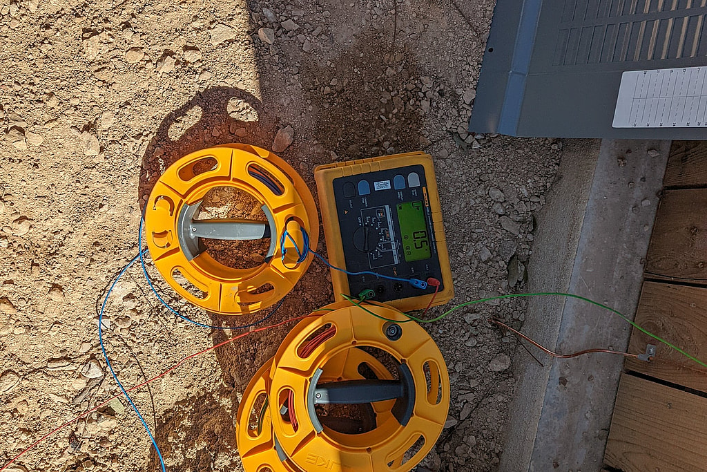
What we can test after the pour
Each visit is a non-destructive site examination, and each report states plainly that nothing was dug up and no concrete was opened. Two tests do most of the work. First, a tracing transmitter connected to the ground bus of the panel puts a tone on the slab reinforcing steel, and the crew walks the slab with a receiver. Hearing the tone over the slab on every outside side shows that the rebar is bonded to the electrical system. Second, a three-pole fall-of-potential test measures the resistance of the Ufer to remote earth.
For the tone the crews use a Radiodetection® PCMx current mapper, and for the fall-of-potential test a Fluke® 1625-2 earth ground tester.
What the sample showed
We reread fifteen reports from 2019 to 2022, for houses in Austin, Pflugerville, Bee Cave, Lakeway and Rollingwood. In thirteen of them the tone was traced across the slab without trouble. Most slabs measured between about 1 and 8 ohms to remote earth, well under the 25 ohm value the code uses for a single electrode, though one measured 30.6 ohms. The failures were mostly elsewhere. In four houses no copper ground rod had been installed at the service, and the report listed one task: install a copper grounding electrode near the main service panel. Where rods were present they measured from 1.5 to 38.6 ohms, and where the electrode system stayed above 25 ohms the task was to add rods until it fell below. One 2022 job had a carport on its own slab, and its reinforcing steel measured 224 ohms to the panel ground, so the task was to make sure a Ufer connection was properly installed there.
The two slabs where the tone did not trace cleanly both had plain explanations. At one house the first test was connected at the panel, but the Ufer connection was at the back of the slab, far from the panel, and the long path weakened the signal. Connected again next to the Ufer, the tone came through strongly all around the foundation, and no fix was needed. The other was that carport: a short stub of rebar sticking out of the ground was not tied to the slab steel at all. After the work, a second visit traced the tone over the whole carport slab, which then measured about 14 ohms. In all, seven of the fifteen first reports listed at least one fix.
Reports the inspector can use
Each report carries the city permit number, the instruments and their calibration dates, the measured values with the test figures, and a pass or fail line for the ground system resistance and for the slab bonding. When something fails, the task is written so the electrician knows exactly what to install before the inspector returns.
If a slab has been poured before the city’s electrical slab inspection, the City of Austin can ask for an alternate method of compliance instead. On one 2019 job, the city’s correction notice asked the electrical contractor for a questionnaire, a letter sealed by a licensed engineer and the engineer’s inspection report, naming the test instrument and its calibration date. Our reports are written to supply that record; accepting it remains the city’s decision.
What the code asks of a Ufer
NEC® 250.52(A)(3) describes the concrete-encased electrode: at least 20 feet of bare steel reinforcing bar of at least 1/2 inch diameter, or bare copper conductor not smaller than 4 AWG, encased in at least 2 inches of concrete that is in direct contact with the earth. In new construction, NEC 250.50 requires a concrete-encased electrode that is present to be bonded into the grounding electrode system. A single rod, pipe or plate electrode that does not measure 25 ohms or less needs a supplemental electrode under NEC 250.53(A)(2), which is where the 25 ohm value in these reports comes from.
How a fall-of-potential test works
The tester drives a current probe well away from the electrode and a potential probe between the two, and reads resistance from the injected current and the measured voltage. With the potential probe at about 61.8 percent of the distance to the current probe, the reading comes close to the true resistance of the electrode to remote earth, provided the probes are far enough out that their zones of influence do not overlap. Moving the potential probe a little each way and checking that the reading holds steady is the usual way to confirm the setup. The method is described in IEEE 81.
To see why the potential probe goes at 61.8 percent, try the fall of potential figure. The code background is covered in our Ufer ground article.
Related services
Our current program for builders has its own write-up, the Austin residential grounding program. The service itself is described under residential inspections.
Electrical power
More projects in this practice
Norman, OK
Airport Grounding Testing, Norman
Ground testing
Temple, Grand Prairie and Humble, TX
Arc Flash Studies at Manufacturing Plants in Temple, Grand Prairie and Humble
Arc flash, coordination
Hattiesburg, MS, plus AZ, WA and TX
Arc Flash Studies for Four Plants in Four States
Arc flash, labels
Get your project started
We typically respond within one business day.