Selected Projects
Cathodic Protection Design for a Federal Installation, Central Oklahoma (2026)
We typically respond within one business day.
Project at a glanceDE-PRJ-8115
- Practice
- Corrosion and CP
- Location
- Oklahoma
- Service
- CP design
- Client
- Confidential
Cathodic Protection Design for a Federal Installation, Central Oklahoma (2026)
We completed this cathodic protection (CP) design in 2026 for piping systems at a federal installation in central Oklahoma. The client’s details are confidential.
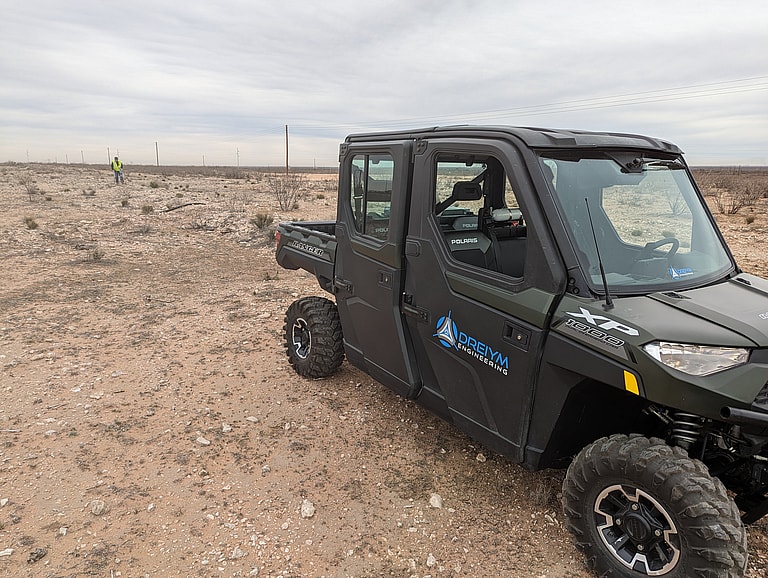
Cathodic protection hardware in service. On a federal job the engineering is the same, with a review process added on top.
Where buried pipe loses metal
Buried metal piping corrodes electrochemically. Current leaves anodic areas on the pipe surface and discharges into the soil around it, and the pipe loses metal wherever that happens. Coating is the first thing between the pipe and the soil, but no coating is perfect, and small defects called holidays leave bare steel exposed. Cathodic protection supplies current to the structure, so the exposed steel at those defects collects protective current instead of corroding. The job is to get enough current to every part of the system and keep the protection measurable and maintainable over time. All of that has to fit within the limits of a facility that’s still operating.
Writing the design for federal reviewers
A federal project brings a layer of process that private projects often don’t need. The design usually moves through set review stages, with formal rounds of comments and responses, so the design intent has to be written down clearly enough for reviewers who weren’t part of the original site discussions. The design also has to state how it conforms to the government’s facilities criteria and to recognized industry standards, including AMPP® (formerly NACE) standards for cathodic protection. Any deviation gets identified and justified in writing. Calculations, drawings and specifications follow prescribed formats. The basis of design is recorded too, so a future engineer can see why each decision was made. None of that changes how buried pipe corrodes, but it does change how the engineering is presented and checked, and what has to be kept on file.
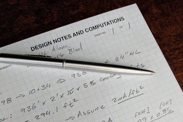
A design calculation sheet working out current demand from pipe surface area, coating condition and an assumed current density. When a facility has to keep running, that sizing gets settled on paper before anything is installed in the field.
Fitting the system into a running facility
At an existing installation, everything already in the ground limits the design. Current requirements can’t be set until the design has pinned down what’s there: which piping is coated and how well, whether the system is electrically continuous, and what else shares the soil. Structural steel, reinforced concrete foundations and copper grounding systems are all in electrical contact with that soil. They’ll collect protective current meant for the piping, so the design either isolates them or allows for that drain when it sizes the system.
Then there’s the anode bed, and where to put it. It has to sit where its current can spread usefully, and far enough from foreign structures that it won’t cause interference. It also has to go on ground the facility can give up. That rules out anywhere under future construction or in a traffic pattern, and the spot has to be reachable for maintenance. When surface space is scarce, a deep anode bed can put the current source below the congestion, at the cost of a more complex installation. Cable runs have to cross a working site, and the outage windows for tie-ins are usually short and scheduled well in advance.
Where the test stations go decides how useful the system is to the facility in the years ahead. The people who monitor it won’t be the people who designed it, and they’ll be reading it once a year for decades. So the stations have to go where their readings represent the whole system. Each one needs to be identified clearly enough that a reading can be matched to a structure years later, and placed where it can be reached safely during normal operations. Our cathodic protection design practice plans for those decades of readings as part of the deliverable.
Our scope at the installation
We designed the cathodic protection for the installation’s piping systems. Current requirements came from engineering calculations, and we laid out the protective current system and its connections to the piping. Test stations were specified so the protection levels can be verified after installation. We prepared the drawings, specifications and calculation packages to the documentation standard that federal design reviews expect. Licensed Professional Engineers oversaw the design, and AMPP® (NACE) certified cathodic protection personnel handled the corrosion-specific parts of the work.
After the design is handed over
Corrosion on buried piping is slow and out of sight, and by the time a failure shows up, the metal is already gone. A correctly designed system that can be verified in the field will protect the piping for the long term. When it’s thoroughly documented, it also leaves the owner a record to draw on for future reviews, audits and maintenance planning. If your facility depends on buried piping, federal or not, our engineers can help through our cathodic protection design practice. You can read about more of our work in the state on our Oklahoma page.
Corrosion and CP
Related projects
Tulsa and Del City, OK
Tulsa and Del City Water-System CP Designs
CP design
Central Texas
Galvanic CP for Condenser Water Piping at a Military Installation, Central Texas
CP design, galvanic anodes, installation
Freeport, TX
Wharf CP Evaluation, Redesign and Commissioning, Freeport
CP design, testing
More work in: Oklahoma
Get your project started
We typically respond within one business day.