Corrosion and Cathodic Protection
5 Types of Cathodic Protection Testing Equipment
The cathodic protection testing equipment a CP survey uses: reference electrode, voltmeter, multimeters and soil resistivity meter, and what each measures.
Reach out to Dreiym Engineering for any Corrosion, Electrical or Forensic Questions.
Contents
A cathodic protection system uses electricity to prevent metal structures like pipelines from corroding. The system creates an electrochemical cell using the corrosive metal as the cathode, with a sacrificial metal acting as the anode to collect corrosion. Keeping it working takes the right cathodic protection testing equipment.
Key takeaways
- Regulated pipelines need a CP survey at least once each calendar year, at intervals not exceeding 15 months, and regulated underground storage tanks need testing at least every three years.
- A copper sulfate half-cell, also called a portable reference electrode, provides the constant reference for potential readings.
- A voltmeter that reads in millivolts measures the structure-to-electrolyte potential, which is compared against AMPP SP0169 criteria.
- Multimeters with selectable input resistance or high impedance, and a soil resistivity meter, round out the equipment.
- A basic potential survey kit is a copper/copper sulfate reference electrode and a high input impedance digital voltmeter, with test leads and a reel.
Want the testing done for you? See our cathodic protection testing services: potential readings at every test station, rectifier inspections and bond checks, compared with the applicable criteria.
If you have a cathodic protection system in place, it’s important to test it regularly: regulated pipelines require a CP survey at least once each calendar year, at intervals not exceeding 15 months (49 CFR 192.465), while regulated underground storage tanks require testing at least every three years (40 CFR 280.31). There are a few types of cathodic protection testing equipment the specialist may use; let’s look at how each of them works.
Copper Sulfate Half-Cell
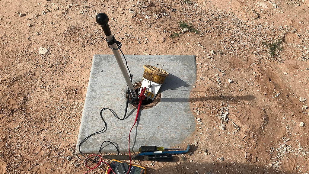
This piece of equipment is also called a portable reference electrode. When the cathodic protection specialist tests your CP system, they will insert the copper sulfate half-cell partway into the soil and connect it to a voltmeter. Reference electrodes are used to define a constant potential when measuring cathodic protection.
Portable Voltmeter
A voltmeter that gives readings in small measurements, like millivolts, is an indispensable tool for testing cathodic protection. The voltmeter connects the protected structure to a reference electrode to measure the structure-to-electrolyte potential, which the specialist compares against AMPP SP0169 criteria to see how well the CP system is protecting the structure from corrosion.
Cathodic protection interference is one reason readings are taken with interrupters: a nearby rectifier can shift a reading on a pipeline that is not its own.
Where the reference cell sits matters as much as the meter: drag it in the figure below and watch the on reading change while the instant-off reading holds.
Over the pipe, the cell is as close to the steel as it gets from the surface, so the on reading carries the least IR drop. The instant-off reading, taken with the rectifier interrupted, removes the rest.
Readings at each position
| Cell position | On | Instant-off | IR drop |
|---|---|---|---|
| 96 ft from the pipe, away from the anode bed | −1,065 mV | −880 mV | 185 mV |
| 72 ft from the pipe, away from the anode bed | −1,059 mV | −880 mV | 179 mV |
| 48 ft from the pipe, away from the anode bed | −1,050 mV | −880 mV | 170 mV |
| 24 ft from the pipe, away from the anode bed | −1,033 mV | −880 mV | 153 mV |
| Over the pipe | −974 mV | −880 mV | 94 mV |
| 24 ft from the pipe, toward the anode bed | −1,048 mV | −880 mV | 168 mV |
| 48 ft from the pipe, toward the anode bed | −1,085 mV | −880 mV | 205 mV |
| 72 ft from the pipe, toward the anode bed | −1,129 mV | −880 mV | 249 mV |
| 96 ft from the pipe, toward the anode bed | −1,232 mV | −880 mV | 352 mV |
| 108 ft from the pipe, toward the anode bed | −1,423 mV | −880 mV | 543 mV |
Selectable Input Resistance Digital Multimeter
Cathodic protection analysts use a couple of different types of multimeters when testing CP systems. A multimeter with selectable input resistance allows the specialist to test the resistance of the circuit that keeps your pipes from corroding.
High Impedance Digital Multimeter
Resistance and impedance, while often used interchangeably, refer to different elements of a cathodic protection circuit. A high impedance digital multimeter measures the opposition of the flow of a current through a conductor. This tool is especially handy when dealing with the soil around the CP system, as soil resistivity can contribute to inaccurate readings.
Soil Resistivity Meter
Speaking of soil, cathodic protection experts need to know how the ground itself conducts electricity in order to get accurate CP readings. A soil resistivity meter uses probes stuck in the ground at regular intervals to measure how strongly it resists electrical current activity.
A Typical Cathodic Protection Test Kit
A basic potential survey kit is a copper/copper sulfate reference electrode and a high input impedance digital voltmeter or multimeter, with test leads and a reel long enough to reach the test stations. What many people call a cathodic protection meter is usually that high impedance digital voltmeter used with the reference electrode. Instant-off readings add current interrupters, synchronized by GPS when more than one rectifier affects the structure. Close interval surveys add a data logger and a trailing wire. Soil resistivity work uses a four-pin resistivity meter, and rectifier inspections use a clamp meter or the rectifier shunt to check the output current.
If your pipeline’s cathodic protection system is due for an inspection, call Dreiym Engineering to enlist the expertise of certified professionals. Our simple, direct approach utilizes several types of cathodic protection testing equipment and years of firsthand experience in the field.