Consulting Areas
Pipeline Current Mapping (PCM)
We typically respond within one business day.
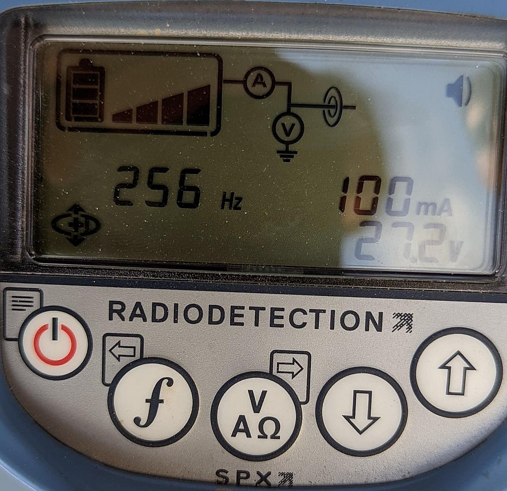
What a current mapping survey measures
A pipeline current mapper puts a low frequency alternating current signal on a buried pipe from a transmitter, and a receiver carried along the route measures the magnetic field the signal produces. From that field the receiver finds the line, estimates its depth and measures how much of the signal current is still on the pipe. Radiodetection® describes its system as applying a very low frequency signal and taking regular measurements along the line to find where current is lost. This is the alternating current current attenuation survey, often shortened to ACCA.
On a well-coated, electrically isolated pipeline the current falls off slowly and evenly with distance. Where it drops sharply, current is leaving the pipe: through coating damage, a contact with another metal structure, a shorted casing or an insulating joint that no longer isolates.
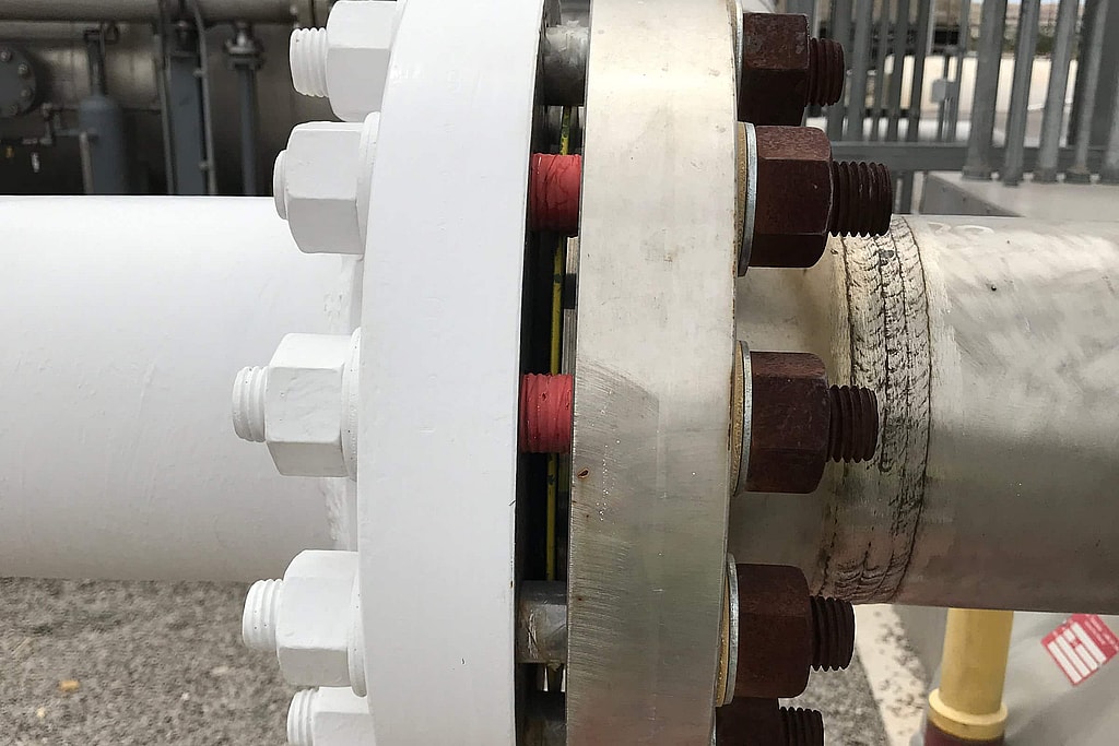
How a current attenuation survey works
The survey starts where the transmitter can be connected to the line. At a rectifier, the pipe and anode cables are disconnected from the rectifier and the transmitter takes their place, with its signal lead on the pipe cable and its return lead on the anode cable. Where there is no rectifier, the transmitter can be connected across an insulating joint, using the pipe on the far side as its ground, or to a sacrificial anode at a test station. Radiodetection® calls for a transmitter ground of less than 20 ohms. The rectifier is switched off first, and only people qualified to work on rectifiers disconnect CP cables.
The transmitter puts a 4 Hz mapping signal on the pipe together with a higher locating frequency. The receiver uses the locating frequency to find the line and its depth, and a magnetometer in its foot measures the 4 Hz current. The receiver allows for depth, so a change in depth alone does not change the current reading. At such a low frequency the signal spreads and attenuates almost the same way as the cathodic protection current from the rectifier, so where the mapping current leaves the pipe is close to where CP current leaves it.
The crew walks the route and takes readings at a set spacing. Each saved reading holds the current and the depth, and a position where the receiver has its GPS option or is paired with an external GPS. Readings are kept away from tees, bends and sudden changes in depth, where the magnetic field is distorted. If the receiver’s peak and null locates differ by more than about 6 inches, the field is taken to be distorted and the reading is moved.
Reading the current profile
The result is a plot of signal current against distance from the transmitter. How fast the current falls depends on the condition of the coating, the resistivity of the soil and the electrical resistance of the pipe, and the shape of the curve shows where to look next.
- A slow, even decline. Coating in good condition. Some steady loss along an older line is normal.
- A steeper slope over one stretch. Poorer coating over that stretch, which takes more current per foot than the sections on either side.
- A sudden step down. Current leaving at one place, through a large coating defect or a short or contact with another pipe, cable or structure. Sacrificial anodes connected straight to the pipe also show up as large losses.
- Lower current in one measurement section only. The pattern of a poorly coated steel shield in contact with the pipe, such as a shorted casing.
- Little or no loss where some is expected. Either very good coating, or dry or rocky ground that is shielding the signal.
Current is plotted in decibels (dBmA) as well as milliamps. On a milliamp scale the loss looks largest near the transmitter and smaller farther away, so equal defects show as shrinking steps. On a decibel scale an even loss becomes a straight line and equal defects give equal steps, so the loss rate, in decibels per unit length such as dB/m or dB per 100 feet, can be compared fairly from one section to the next.
Two cautions apply. Within the first 30 to 50 meters of the transmitter ground, readings can be misleading because the signal current in the soil there runs opposite to the current on the pipe, so that stretch is surveyed from another connection point. And around a coating defect, the reading can dip and then rise for a few meters on either side as fault current in the soil distorts the field, while a contact with a crossing pipe or cable usually shows the dip without the rise.
Our equipment
We use a Radiodetection® PCMx® pipeline current mapper on pipeline field surveys to trace a buried line and measure the current on it. The same field visit can include locating the line, measuring depth of cover and the potential surveys a cathodic protection program needs.
What current mapping is used for
- Confirming the route of a line before other surveys or excavation
- Ranking sections of a line by coating condition from the rate of current loss
- Finding contacts with foreign pipelines and other structures, and shorted casings at road and rail crossings
- Checking insulating joints and flange kits that are supposed to isolate a line
- Supporting the indirect inspection step of external corrosion direct assessment (ECDA), where federal rules require at least two different but complementary indirect inspection tools for each ECDA region
Need a line mapped before an ECDA, a dig or a coating survey? Request a free quote. We typically respond within one business day.
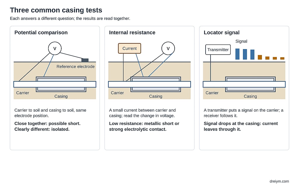
What it does not tell you
Current mapping shows where signal current leaves the pipe. It does not show whether the steel at that spot is corroding or protected, and it does not pinpoint a single small coating defect. For that, the usual next steps are an ACVG survey or a DCVG survey to locate and grade coating faults, and a close interval survey to measure cathodic protection levels along the line. Readings can also be distorted where other lines run close by, so findings are checked before anyone digs.
Current mapping data are most useful alongside the rest of the record. On one Central Texas crude oil pipeline, an earlier current mapping survey had flagged possible stray current locations, and our troubleshooting combined those results with interrupted surveys and continuity tests to find the real cause of low readings.
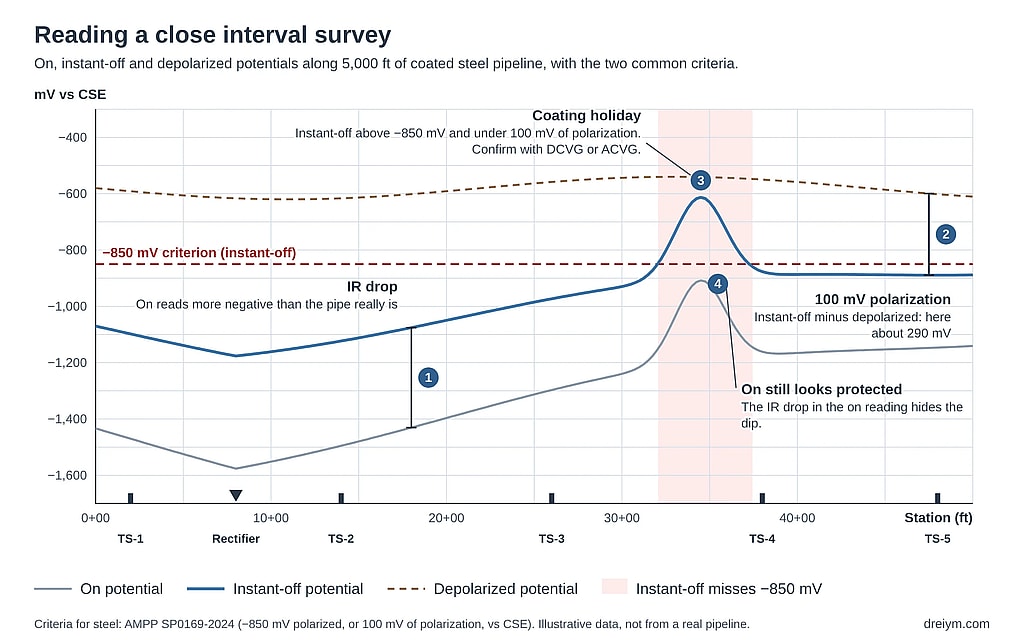
Current mapping alongside CIS, DCVG and ACVG
No single survey answers every question about a buried line. That is why federal rules for external corrosion direct assessment call for at least two different but complementary indirect inspection tools in each ECDA region, following AMPP® (NACE) SP0502. Each tool answers a different question:
- Current mapping (ACCA) covers long sections quickly, ranks coating condition by the rate of current loss and finds contacts and shorts.
- ACVG uses an A-frame on the ground over the line to pinpoint individual coating faults and compare their size. With the PCMx®, ACCA and ACVG readings can be taken separately or together in one pass.
- DCVG locates coating defects, grades each one by its percent IR and shows whether the steel there is corroding or protected.
- A close interval survey reads the pipe-to-soil potential every few feet to show whether cathodic protection meets its criteria along the line.
A practical order is to map the current first, send the A-frame or a DCVG crew to the stretches where current is lost, and run a close interval survey where protection levels are in doubt. The results of all the surveys are then lined up by station and position, so that excavation goes first to the places where they agree.
What you receive
- A plot of signal current against distance for each section surveyed, in milliamps and decibels, with the loss rate marked
- A table of readings with position, current and depth, and notes on test stations, crossings, casings and other features
- A map of the surveyed route from the logged positions
- A ranked list of the places where current is lost, with the likely cause of each and the follow-up we recommend: an ACVG or DCVG survey to pinpoint a fault, an isolation or casing test, or an excavation
- Findings reviewed by a licensed Professional Engineer, and PE-stamped where required
When the same right-of-way also needs pipeline locating or depth of cover, those readings come from the same walk of the line.
Frequently asked questions
What is a pipeline current mapping survey?
A survey that puts a low frequency signal on a buried pipe and measures how much of that signal current is still on the pipe at points along the route. Where the current falls off quickly or drops suddenly, it is leaving the pipe through coating damage or a contact with other metal. It is also called a PCM survey or an ACCA survey.
What is the difference between ACCA and ACVG?
An ACCA survey measures the signal current on the pipe and how it falls with distance, which ranks coating condition and points to contacts. An ACVG survey measures the voltage gradient in the soil with an A-frame to pinpoint individual coating faults. Both use the same kind of transmitter signal, and the PCMx® can record both in one pass.
What does a sudden drop in PCM current mean?
Current is leaving the pipe at that point. Likely causes are a large coating defect, a short to a casing, a contact with a foreign pipeline or cable, or a sacrificial anode connected straight to the pipe. A follow-up with an A-frame, or an isolation test, narrows it down before anyone digs.
Why is PCM current plotted in decibels?
Because on a milliamp scale equal defects look smaller the farther they are from the transmitter. In decibels an even loss is a straight line and equal defects give equal steps, so the loss rate in dB per unit length can be compared between sections.
Does current mapping show whether the pipe is protected?
No. It shows where signal current leaves the pipe, which follows where CP current goes, but it does not measure the pipe-to-soil potential. A close interval survey measures protection levels along the line.
Talk to an engineer
Planning a coating or CP survey, or chasing a current loss? Request a free quote. We typically respond within one business day.
Get your project started
We typically respond within one business day.