Consulting Areas
Cathodic Protection Design
We typically respond within one business day.
Cathodic protection design Illustrative
Turn up the rectifier and watch the pipeline answer
A rectifier pushes current through the soil and onto a buried pipeline. The pipe close to it gets plenty; the far end gets what is left. How fast the protection fades depends mostly on the coating. Set the taps, change the coating or add a second station, and see which miles meet the −850 mV criterion.
Part of the line is still short of −850 mV. Raise the taps: tap C6 protects the whole line.
- Rectifier output
- 5.0 V, 1.10 A
- At the rectifier, mile 0
- −854 mV
- Far end, mile 10
- −710 mV
- Miles meeting −850 mV
- 0.1 of 10
- Miles past the upper limit
- None
Short of −850 mV Meets −850 mV Past the upper limit Current through the soil
Pipe-to-soil potential with the current on (model), mV vs CSE
Readings at each test station
| Mile | Potential, mV | Result |
|---|---|---|
| 0 | −854 | Meets −850 mV |
| 1 | −823 | Short of −850 mV |
| 2 | −797 | Short of −850 mV |
| 3 | −775 | Short of −850 mV |
| 4 | −757 | Short of −850 mV |
| 5 | −742 | Short of −850 mV |
| 6 | −730 | Short of −850 mV |
| 7 | −721 | Short of −850 mV |
| 8 | −715 | Short of −850 mV |
| 9 | −712 | Short of −850 mV |
| 10 | −710 | Short of −850 mV |
Why coating decides it
Current enters the pipe wherever the coating lets it in. On a well-coated line very little current protects many miles. On a poorly coated line the current is used up close to the rectifier, so the far end starves.
Why not just turn it up
Raising the taps pushes the whole curve down, near end first. With one station on the fair coating, only tap C6 brings the far end to −850 mV without pushing the pipe near the rectifier past the upper limit, where too negative a potential can damage the coating; one tap more and it is past. On the poor coating even the top tap leaves the far end short. Then the answer is another station, more groundbed, or better coating.
What a survey adds
The model assumes even soil and even coating. A close interval survey measures the real curve every few feet, interrupted so the IR drop is taken out, and finds the low spots this model cannot know about.
Model: transmission-line attenuation on a finite line with insulated ends (pipe resistance from the steel section, coating conductance per mile set by the coating choice), groundbed and cable resistance 2.5 ohms, back voltage 2.0 V, taps 0.5 V apart up to 12 V; with two stations both currents are solved together.
Cathodic Protection Design Services
Cathodic protection design is the engineering that turns site measurements into a working corrosion control system: how much current a structure needs, which anodes or The power unit of an impressed current system. It converts AC power to adjustable DC current and drives it through the anodes to the structure.See the glossary will supply it, where the The anodes of an impressed current system, buried together in the earth, usually in carbon backfill. A deep anode groundbed places them in a drilled hole well below the surface soil.See the glossary goes, and where the A post or flush box at the structure with wires bonded to it, where readings of potential and current are taken without digging.See the glossary sit so the system can be proven for decades. Get the sizing wrong and you pay for it out of the operating budget every year after.
Dreiym Engineering prepares galvanic (sacrificial) and A CP system that uses a rectifier to drive DC current from long-life anodes through the soil to the structure. The output can be adjusted, which suits long pipelines, bare steel and high current demand.See the glossary designs under licensed Professional Engineers for underground and submarine pipelines, aboveground and underground storage tanks, water systems, plant piping and marine structures. You get drawings, specifications and calculations, PE-stamped where required, that your contractor can bid and build from, or that we can install ourselves. Design is one part of our cathodic protection services.
New to cathodic protection? Our cathodic protection guide puts our articles, calculators and services in the order to read them.
For a free quote on a CP design, contact us. We typically respond within one business day.
CP Surveys
Design inputs we measure first
We gather data on the structure before picking any anodes or a rectifier. These inputs drive every number in the design.
- How strongly soil resists electric current, in ohm-centimeters (ohm-cm). Low resistivity usually means more corrosive soil. It also sets how much current CP anodes can deliver and how a groundbed is sized.See the glossary and corrosivity: A soil resistivity test with four pins in a straight line at equal spacing. Current flows between the outer pins and voltage is read between the inner two; the pin spacing sets roughly how deep the reading looks (ASTM G57, IEEE Std 81).See the glossary resistivity along the route or around the structure, at more than one pin spacing, plus lab pH, moisture, chlorides, sulfates and bacteria through our soil corrosivity analysis.
- Coating and surface area: coating type and condition set the current requirement. On an existing structure, a current requirement test measures it directly.
- Continuity and isolation: gasketed joints, foreign connections, grounding grids and reinforced concrete decide what the current will actually reach.
- Interference and AC exposure: foreign pipelines, DC rail and parallel transmission lines, checked through our interference testing and AC interference mitigation work.
- Climate: frozen ground raises resistivity sharply, so in cold regions anodes go below frost depth and rectifiers are sized for the seasonal swing.
- Records: existing drawings, earlier survey data and the operating history of any CP system already in place.
How we put a CP design together
The steps hardly change between a pipeline, a tank farm and a water system.
- Site and records review: drawings, coating condition, earlier survey data and the history of any existing system.
- Field measurements: soil resistivity, The structure-to-soil potential before any CP current is applied, or after the structure has fully depolarized. It is the baseline for the 100 mV polarization criterion.See the glossary and continuity, plus interference testing where foreign lines, rail or powerline corridors share the ground.
- Calculations: current demand from surface area and coating quality, anode selection and life, groundbed sizing and placement, and rectifier sizing with margin for seasonal swings and coating degradation.
- Construction documents: drawings, specifications and installation details, PE-stamped where required, that a contractor can bid and build from, including the commissioning criteria the finished system has to meet.
- Installation and energizing: we install the system or observe your contractor’s work, then test and adjust it when it is first turned on and log baseline data for your compliance records.
Galvanic or impressed current?
The resistivity data and the current demand decide. Neither is better in general; each has a range where it is the cheaper way to meet criteria.
- An anode of a metal more active than steel, such as magnesium, zinc or aluminum, connected to the structure so the anode corrodes instead of the steel. It needs no outside power.See the glossary of magnesium, zinc or aluminum need no power and cost less up front. They suit small, well-coated structures, lower-resistivity soils and submerged service. Unless otherwise specified, we design them for a 20-year life.
- Impressed current (ICCP) uses a rectifier and long-lived anodes. It costs more up front and needs regular rectifier inspections, but the output can be turned up or down. It suits long pipelines, bare or poorly coated steel, high-resistivity ground and high current demand. Unless otherwise specified, we design it for 30 years.
Where surface soils resist current flow, or there isn’t room near the structure, we design deep anode groundbeds, with the active anode column typically at least 50 feet below grade. For a fuller comparison, see the two types of cathodic protection systems.
Groundbed design services
The groundbed is the anode assembly that sends protective current into the soil, and where it sits decides how evenly that current reaches the structure. We design the three common layouts:
- Shallow (conventional) groundbeds: vertical or horizontal anodes in coke breeze within a few feet of the surface, set back from the structure.
- Distributed (linear) groundbeds: anodes spread along the structure, for congested plant sites and well-coated lines where interference has to stay low.
- Deep anode groundbeds to AMPP/NACE SP0572: an active anode column typically at least 50 feet below grade in lower-resistivity strata, with carbonaceous backfill and a vent pipe for the gases the anodes produce.
Each groundbed design starts from soil resistivity measured at depth, the current requirement and what else is buried nearby. It sets the anode count and spacing, the backfill, the groundbed resistance, the cable and junction box details and the rectifier output, PE-stamped where required.
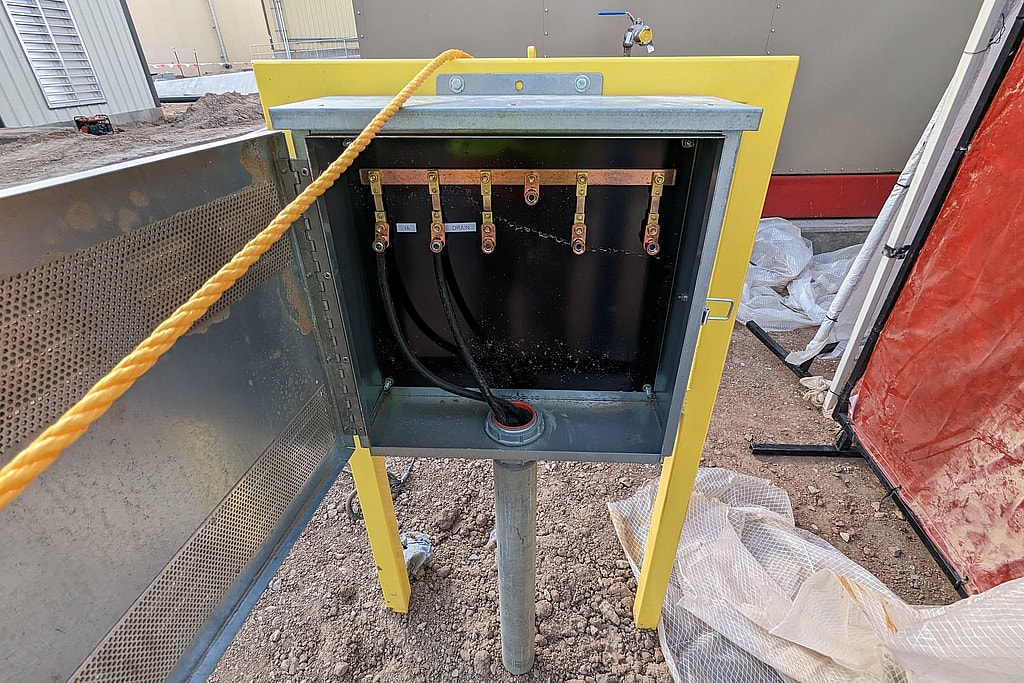
Anode junction box with bus bar
Existing systems that fail their surveys
We also check existing CP systems and give you a list of the repairs, maintenance or replacements needed to bring a pipeline or tank back to criteria. When a system keeps failing, we find the cause (depleted anodes, lost continuity, shorted isolation, coating failure or interference), design the repair or retrofit, PE-stamped where required, install it if you want us to, and retest, without bringing in a second firm. That diagnosis usually starts with our cathodic protection potential surveys.
CP Designs and Detail Drawings We Produce
- Groundbeds: deep anode groundbeds, conventional groundbeds and distributed anode systems
- Pipelines: underground and submarine pipelines, including transmission, gathering and distribution lines, and plant pipeline networks
- Tanks: aboveground (AST), underground (UST) and elevated storage tank corrosion control
- Water systems: mains, including joint bonding and isolation, and water storage tanks
- Marine cathodic protection for submerged and waterfront structures
- Interference work: DC rail corrosion control, interference analysis and mitigation, and AC interference mitigation
- Monitoring: CP test stations, corrosion coupon and probe monitoring, and remote monitoring
- System safety grounding for CP installations
- Repair and retrofit designs for systems that fail their surveys
Design Deliverables and Construction-Phase Services
Design deliverables
- Calculation package: current requirement, anode selection and life, groundbed resistance and layout, rectifier sizing and attenuation analysis
- Drawings and installation details: groundbeds, cable routing, structure connections, bonds, isolation and test station locations, with every lead identified
- Specifications for anodes, backfill, cable, rectifiers and test station hardware, so substitutions can be checked against the design
- Commissioning criteria the installed system must meet before the contractor leaves
- Basis of design, so a future engineer or reviewer can see why each decision was made, prepared in the formats federal design reviews expect when the work is federal
- PE stamp where required, from licensed Professional Engineers with active and past licensure in multiple states. Dreiym Engineering PLLC holds Texas engineering firm registration F-16324.
Installation, construction-phase services and commissioning
Most underperforming CP systems had a sound design and a poor installation, and by the time anyone looks, the evidence is buried. We install CP systems ourselves, or, when your contractor does the installation, we stay involved through construction: submittal review, observation of anode placement, backfill, cable routing and structure connections, continuity and isolation checks before the trench is closed, and commissioning, with the results recorded as the baseline for every later survey. See our start-up and commissioning services, the Tulsa construction-phase project and cathodic protection commissioning for your construction site.
Cathodic protection design projects
- Marine CP design, Freeport, Texas (2018): current requirements worked out for the immersed surfaces, and anodes laid out for installation
- Federal installation, central Oklahoma (2026): piping CP with specified test stations, delivered as drawings, specifications and calculations for federal review
- Waterlines, Fort Worth and Mansfield (2024-2025): designs sized from field data so commissioning could prove the protection
- Water systems, Tulsa and Del City (2018): joint continuity decided how much of a main the protection could reach
- Laredo and Bryan, Texas (2024-2025): design packages delivered alongside coating surveys in the Permian Basin
Who prepares the design
Our designs are prepared under licensed Professional Engineers and follow AMPP (NACE) practice. Stepan V. Eero, M.S., P.E. is a NACE Cathodic Protection Specialist (CP4), and Brian J. Brackensick, M.S., P.E. is a NACE Cathodic Protection Technologist; our article on cathodic protection engineers explains what each qualification covers. Founded in 2014, Dreiym brings over 30 years of combined experience. Colorado requires a corrosion expert for field-installed UST CP design; our engineers meet that through our Colorado UST program, and we handle cathodic protection design in Colorado from our Westcliffe office.
As an electrical engineering firm too, we handle the power side of a CP project, from electrical design to electrical load analysis. CP protects steel in soil or water; for exposed steel, see atmospheric corrosion.
To start a design, call (866) 621-6920 or contact us for a free quote. We typically respond within one business day.
Soil resistivity Screening
Plot your Wenner four-pin readings
Enter spacing and resistance for two traverses, see apparent resistivity on log axes and a two-layer screening fit, then download the readings as a CSV file.
Open the soil resistivity workbenchFrequently asked questions
What does a cathodic protection design include?
A calculation package (current requirement, anode life, groundbed and rectifier sizing), drawings and installation details, material specifications, test station locations, and the commissioning criteria the installed system must meet, PE-stamped where required.
How do you choose between galvanic and impressed current?
From the measured soil resistivity and the current requirement. Small, well-coated structures in lower-resistivity soil usually get galvanic anodes. Long lines, poorly coated steel, high-resistivity ground or high current demand usually call for impressed current.
What do you need from us to start a CP design?
Drawings of the structure, coating information, any earlier survey data, and the history of any existing CP system. We take the field measurements ourselves: soil resistivity, native potentials, continuity and interference.
Does a cathodic protection design need a PE stamp?
It depends on the jurisdiction, the regulator and the owner’s contract. Colorado’s UST rules, for example, require a corrosion expert (an AMPP-certified specialist or a registered PE with corrosion education and experience) for field-installed CP design. Our designs are PE-stamped where required. See CP specialists vs. licensed engineers.
How long will a cathodic protection system last?
As long as it is designed to. Unless otherwise specified, we design galvanic systems for a 20-year life and impressed current systems for 30 years. Anode mass or rectifier capacity is sized for that target, with allowance for coating degradation over those years.
Do you install cathodic protection systems?
Yes. We install CP systems as well as designing, testing and commissioning them. If your own contractor does the installation, we review submittals, observe the work, check continuity before backfill and commission the system against its design criteria.
Related Reading
- Three Common Challenges of Comprehensive Cathodic Protection Design
Three challenges in comprehensive cathodic protection design: stray current interference, uneven current distribution and high soil resistivity.
- Deep Groundbed Systems: What They Are & Why They Matter
A deep groundbed reaches low resistivity soil when the surface soil is poor. How deep anode beds are designed and installed, and why they protect pipelines.
- The Role of Anodes in Dependable Cathodic Corrosion Protection
Anodes in cathodic protection: how sacrificial and impressed current anodes protect buried and submerged metal, and how to keep them working.
Related Services
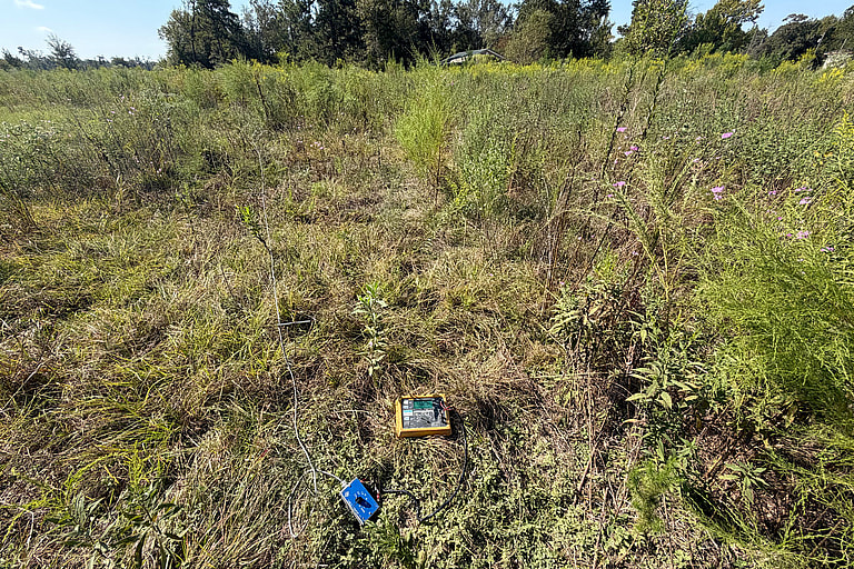
Soil Corrosivity Analysis
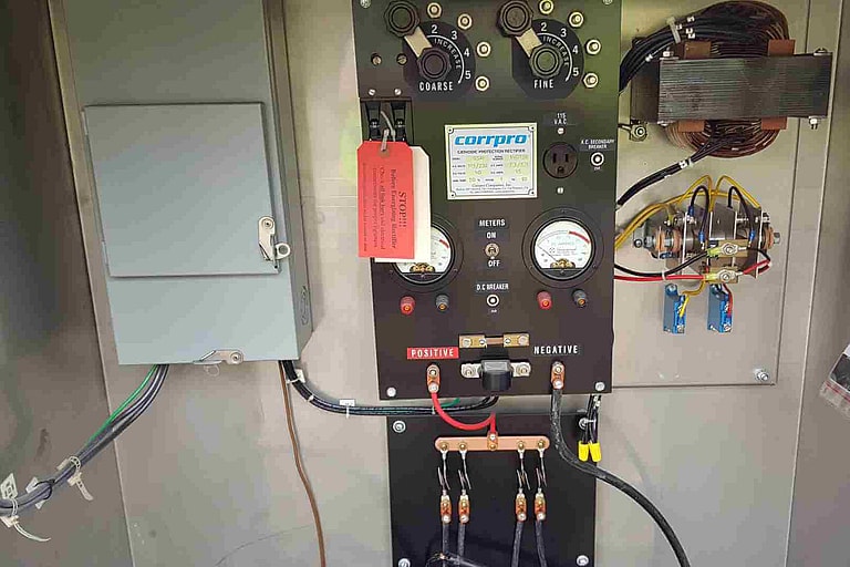
Start-up and Commissioning
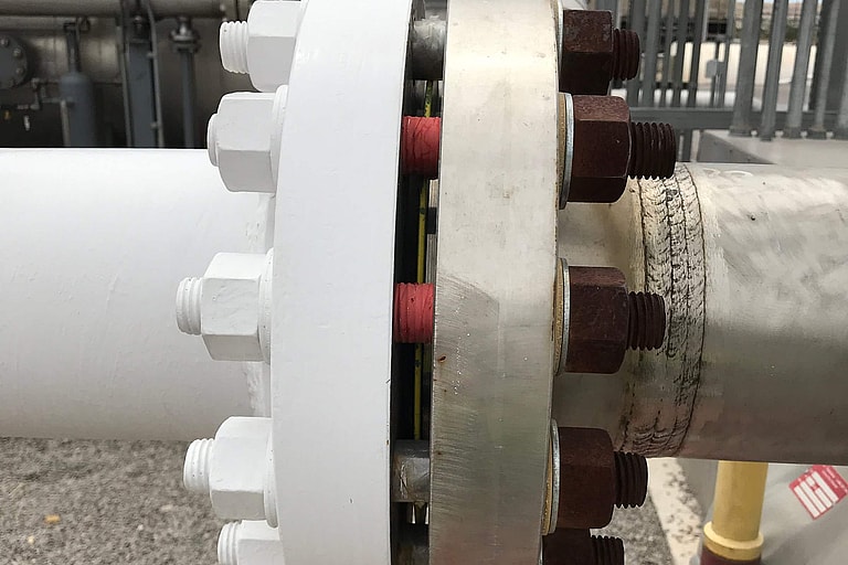
Interference Testing
Project experience
Related projects
Texas, three sites
Galvanic Anode Designs for Steel Casings at Crossings, Texas
CP design
San Antonio, TX
Pump Station Yard Piping CP Design and Testing, San Antonio
CP design, test witnessing
Southeast Texas
CP Design for Twelve Canal Flume Crossings, Southeast Texas
CP design, galvanic anodes
Upper Texas Coast
Flood Gate CP Anode Vent Review, Upper Texas Coast
CP consulting
Fort Worth and Mansfield, TX
Water Line CP Designs, Fort Worth Area and Mansfield
CP design
Austin area, TX
Galvanic CP Design for a Water Storage Tank, Austin Area
CP design
Get your project started
We typically respond within one business day.