Consulting Areas
Soil Corrosivity Analysis
We typically respond within one business day.
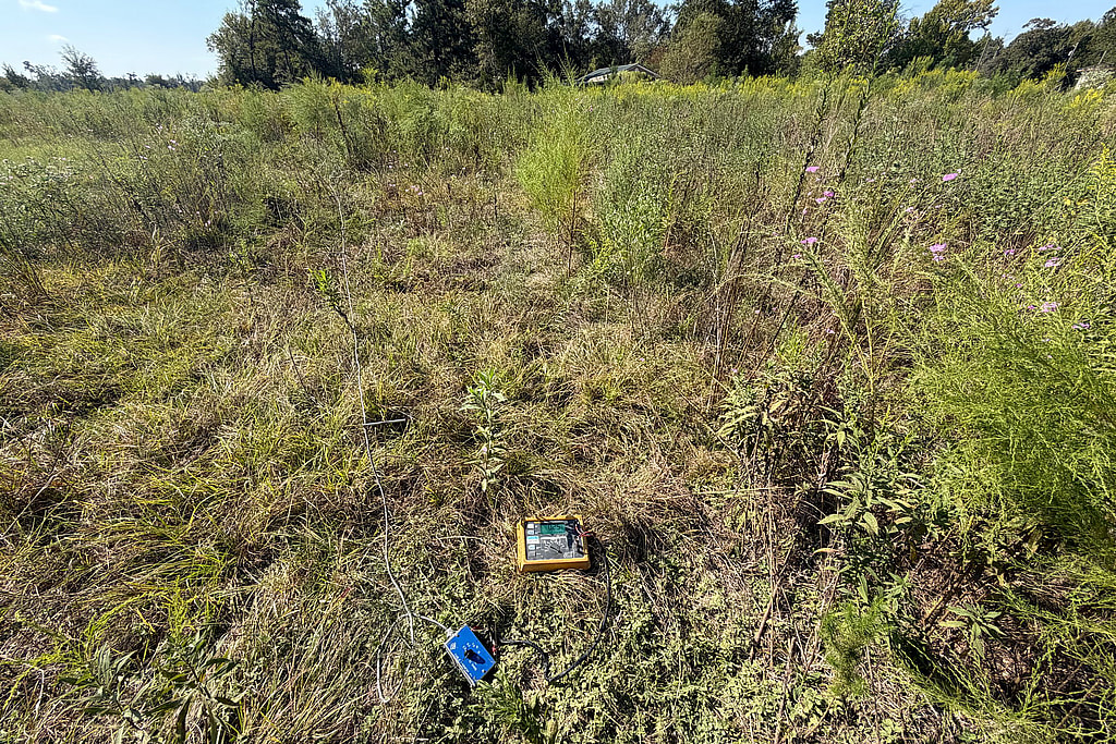
Soil resistivity Screening
Wenner four-pin readings, plotted and fitted
Enter the pin spacing and the meter reading for two traverses at right angles. The workbench plots apparent resistivity and fits a simple two-layer soil model to your readings. It is a screening fit, not a design.
Soil Corrosivity Testing for Buried Pipelines and Tanks
Soil corrosivity analysis measures how aggressive the ground is toward buried steel, iron and other metals. Resistivity, moisture, pH, oxygen, dissolved salts such as chlorides and sulfates, and bacteria all affect how fast a buried pipeline, tank, piling or grounding system will corrode. The results tell you whether the structure needs cathodic protection, which type of system fits and how much current it will need.
You usually can’t change the soil a structure is buried in, and some soils are highly corrosive. A design that accounts for them from the start costs far less than finding the problem after a pipe or tank starts to leak.
Contact us for a free quote. We typically respond within one business day.
CP Surveys
Soil testing is the first step in designing corrosion control. Our corrosion engineers use the results to choose materials and coatings, to decide between An anode of a metal more active than steel, such as magnesium, zinc or aluminum, connected to the structure so the anode corrodes instead of the steel. It needs no outside power.See the glossary and impressed current cathodic protection design, and to size anodes and The anodes of an impressed current system, buried together in the earth, usually in carbon backfill. A deep anode groundbed places them in a drilled hole well below the surface soil.See the glossary. Field resistivity is usually measured with the A soil resistivity test with four pins in a straight line at equal spacing. Current flows between the outer pins and voltage is read between the inner two; the pin spacing sets roughly how deep the reading looks (ASTM G57, IEEE Std 81).See the glossary described in ASTM G57, Standard Test Method for Measurement of Soil Resistivity Using the Wenner Four-Electrode MethodThe standard procedure for measuring soil resistivity with four equally spaced pins in the field, or with a soil box on samples in the lab.Plain-language summary, not the standard’s wording.See the glossary, at pin spacings chosen to sample the depths of the structure and the planned groundbed.
The same Wenner measurements are used in grounding design. See ground testing and commissioning.
Where this matters most: energy-sector cathodic protection in North Dakota, where seasonal freezing moves How strongly soil resists electric current, in ohm-centimeters (ohm-cm). Low resistivity usually means more corrosive soil. It also sets how much current CP anodes can deliver and how a groundbed is sized.See the glossary enough to change the design.
Soil resistivity testing in the field (Wenner four-pin, ASTM G57)
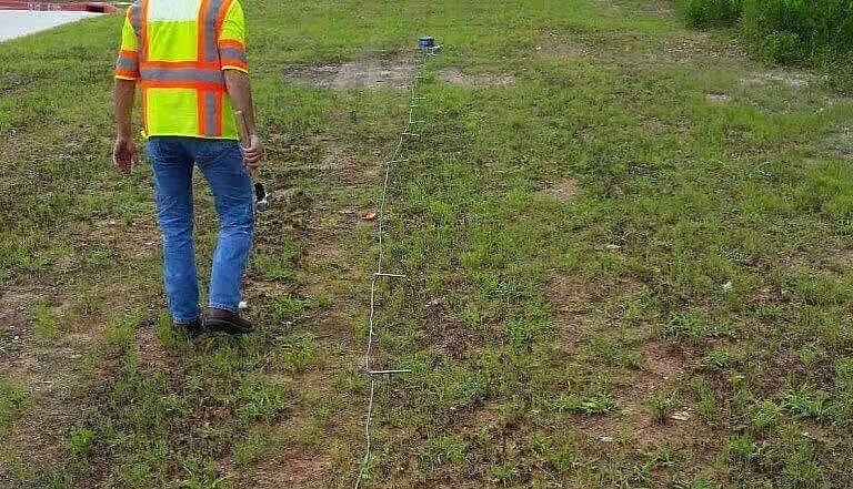
Our soil resistivity testing services use the Wenner four-pin method in ASTM G57: four pins in a straight line at equal spacing, with the reading at each spacing reflecting the soil down to about that depth. Readings at several spacings show how resistivity changes with depth, which sets groundbed depth and grounding grid design. Recent field work:
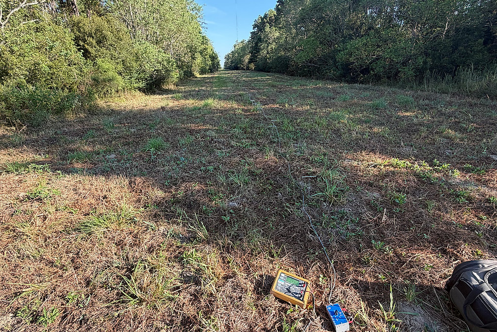
Soil resistivity test in the field
When you request soil corrosivity testing, we mobilize to the site to measure soil resistivity and collect soil samples. The samples are tested in a laboratory for:
- pH
- Moisture content
- Laboratory resistivity
- Chlorides and sulfates
- Bacteria that can accelerate corrosion, such as Bacteria that live in oxygen-poor soil and water and produce hydrogen sulfide, which speeds up corrosion of steel and iron. Their activity is one form of microbiologically influenced corrosion (MIC).See the glossary
We combine the field and laboratory results with the structure’s material, coating and required life to recommend the most cost-effective protection. Galvanic systems are designed for a 20-year life and impressed current systems for 30 years, unless your project specifies otherwise.
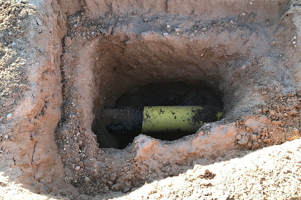
Coated pipe exposed in a bellhole
Get a Quote for Soil Testing
Tell us where the structure is, what it’s made of and when it goes in the ground, and we’ll quote the testing. Quotes are free. We typically respond within one business day.

What makes soil corrosive

Aeration
Aeration is how much air the soil holds between its particles. Sandy, well-aerated soils drain and dry quickly, while clays stay wet and starved of oxygen. Where a pipe runs from one into the other, the difference in oxygen sets up a corrosion cell that attacks the pipe in the poorly aerated soil.

Acidity (pH Levels)
Soils range from roughly pH 2.5 to pH 10. Acidic soils, below about pH 5, are the most aggressive toward steel and iron, and strongly alkaline soils can attack aluminum and lead. pH is read together with resistivity and dissolved salts, not on its own.

Soil Resistivity
Soil resistivity measures how strongly the soil resists the flow of electric current, in ohm-centimeters. It’s the most widely used single indicator of corrosivity: the lower the resistivity, the more easily corrosion current flows. Resistivity falls as moisture and dissolved salts increase, so it can change with the seasons, and it also sets how a cathodic protection groundbed has to be designed. Our article on soil resistivity and corrosion explains the connection.

Temperature
Temperature also plays a role in corrosive potential because temperature impacts soil resistivity. Resistivity climbs slowly as the ground cools, then jumps once the soil water freezes. In the IEEE Std 80 data, a sandy loam that reads about 7,200 ohm-cm at 68°F reads 79,000 ohm-cm at 23°F, more than ten times as high. Cold soil is usually less corrosive, but frozen ground also makes it harder for a cathodic protection system to push current, which is why in cold climates we set anodes below frost depth. As such, the range of soil temperatures at your sites is not something to be ignored.
Frequently Asked Questions
What is soil corrosivity?
How aggressive a soil is toward buried metal. It depends mainly on resistivity, moisture, pH, oxygen, dissolved chlorides and sulfates, and bacteria, and it can vary a great deal along a single pipeline route.
What soil resistivity is considered corrosive?
As a rough guide, soils below about 2,000 ohm-cm are generally treated as highly corrosive and soils above about 10,000 ohm-cm as mildly corrosive or less; published tables differ in between. Resistivity alone doesn’t settle it, because low pH, chlorides, sulfates or bacteria can make a high-resistivity soil aggressive.
When should soil be tested?
Before a pipeline, tank or other buried structure is designed, so the results can set the coating, the cathodic protection and the anode or groundbed design. Testing also helps when an existing system needs more current than expected or a structure has corroded faster than it should.
Do you design the cathodic protection too?
Yes. We use the soil data to design cathodic protection systems, and we install, test and commission them.
Related Reading
- The Relationship Between Soil Resistivity and Corrosion
Soil resistivity and corrosion have an inverse relationship: the lower the resistivity, the more corrosive the soil. Learn what that means for your assets.
- What Determines How Corrosive Your Soil Is?
Aeration, pH, salt content, temperature and resistivity decide how corrosive soil is. Why testing soil before you build protects buried metal.
- The Different Methods of Soil Testing
Compare soil testing methods (pH, moisture, resistivity and Atterberg limits) and how soil corrosivity testing protects pipelines and buried structures.
- Overcoming the Challenges of Corrosion in Shale Deposits: Proven Strategies
Corrosion in shale wells from CO2, H2S and fracking fluids damages equipment fast. Proven protection strategies, from inhibitors to cathodic systems.
Related Services
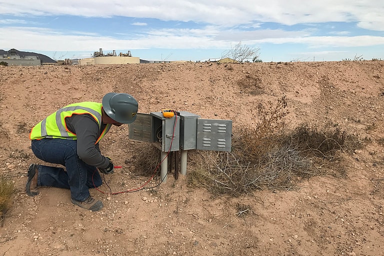
Potential Surveys
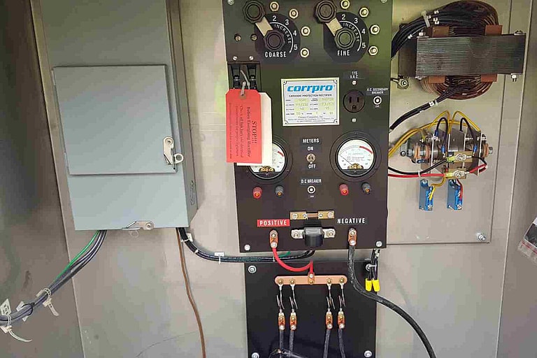
Start-up and Commissioning
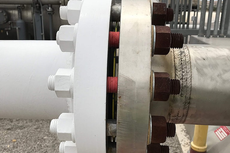
Interference Testing
Project experience
Related projects
Taylor, TX
Soil Corrosivity Memo for a New Industrial Gas Plant, Taylor
Soil corrosivity study
New Braunfels, TX
Soil Corrosivity Study for a Water Line, New Braunfels
Soil corrosivity study
Lake Charles, LA
Pipeline Route Soil Resistivity Survey, Lake Charles
Soil resistivity
Central Texas
Solar Farm Pile Corrosion Testing, Central Texas
Corrosion rate testing
San Antonio, TX
CP Design for Four Water Transmission Lines, San Antonio
CP design, soil testing
Brownsville area, TX
Canopy Pier CP Designs at Two Federal Facilities, Brownsville Area
CP design, soil testing
Get your project started
We typically respond within one business day.