Grounding System Components: The Main Parts of a Grounding (Earthing) System
Grounding system components: electrodes, conductors, bonding jumpers, ground bars and connections, what each one does and how it is tested.
Reach out to Dreiym Engineering for any Corrosion, Electrical or Forensic Questions.
Contents
The main grounding system components (the parts of what many countries call an earthing system) are grounding electrodes in the earth, the grounding electrode conductor that ties them to the service, the bonding jumper that joins the neutral to ground, the equipment grounding conductors that run with every circuit, and the bonding of metal piping and steel, all joined at ground bars by permanent or listed connections. Together these parts limit the voltage lightning and surges can impose. They give fault current a low-impedance path so breakers trip, and they keep exposed metal at a common, safe voltage.
The two types of grounding use these parts differently: system grounding ties the neutral to earth, and equipment grounding gives fault current a path back to the source.
Below we explain what each part does, how the parts work together under Article 250 of the National Electrical Code (NFPA 70), what the 25-ohm rule really requires, and how grounding systems are tested. Section numbers are from the 2017 through 2023 NEC®; check the edition your jurisdiction has adopted.

Interactive explainers: Ufer (concrete-encased) electrode, fall-of-potential test.
The Parts of a Grounding System
Grounding Electrodes
Electrodes are the parts in direct contact with the earth. NEC 250.50 requires bonding every electrode present at a building together into one grounding electrode system. NEC 250.52 lists the types:
Related project: Shock Complaints at Drive-Through ATMs, Florida
- Metal underground water pipe in contact with the earth for 10 feet or more, bonded around water meters and filters. A metal service line can be replaced with plastic without anyone noticing, so a water pipe electrode must always be supplemented by another electrode.
- Metal in-ground support structures, such as steel columns in direct contact with the earth vertically for 10 feet or more.
- Concrete-encased electrodes, often called Ufer grounds: at least 20 feet of 1/2-inch or larger rebar, or bare 4 AWG or larger copper, in at least 2 inches of concrete in a footing or foundation that contacts the earth. Concrete holds moisture, so a Ufer is often the best electrode on a new building.
- Ground rings: at least 20 feet of bare 2 AWG or larger copper encircling the building, buried at least 30 inches deep.
- Rod, pipe and plate electrodes. A driven ground rod needs at least 8 feet in contact with the soil, and steel rods must be at least 5/8 inch in diameter unless listed for less.
- Other listed electrodes and local metal underground systems, such as tanks and well casings.
Metal underground gas piping and aluminum are not permitted as electrodes.
The 25-Ohm Rule for a Single Ground Rod
Under NEC 250.53, a single rod, pipe or plate electrode must be supplemented by an additional electrode unless it has a resistance to earth of 25 ohms or less. The supplement is usually a second rod at least 6 feet away. More spacing helps, because close rods draw on the same soil.
Two points are often missed. The code doesn’t require the pair to reach 25 ohms: once the supplemental electrode is in, the requirement is met whatever the reading, which is why many installers drive two rods rather than test one. And 25 ohms is a code minimum, not a design target. Many owners, utilities, telecom carriers and data centers specify lower values and require testing to prove them. Values of 10 or 5 ohms are common, and critical sites often go lower still.
Grounding Electrode Conductor
The grounding electrode conductor (GEC) connects the electrode system to the electrical system. It typically lands in the service equipment, where the neutral and equipment ground are bonded. A separately derived system, such as a transformer, gets its own GEC connection.
NEC 250.66 sizes the GEC from the largest ungrounded service-entrance conductor, up to 3/0 copper. Where it’s the only connection to a rod, pipe or plate, it needn’t exceed 6 AWG copper. For a concrete-encased electrode, the limit is 4 AWG copper. Installers run a GEC unbroken or splice it only with irreversible compression connectors or exothermic welds. A steel raceway around it needs a bond at both ends.
Main Bonding Jumper and System Bonding Jumper
The main bonding jumper connects the neutral to the equipment grounding conductors and service enclosure at the service. In a panelboard it’s often a green screw or strap; in a switchboard, a bus link. It lets ground-fault current return to the utility transformer through the neutral rather than the earth. The system bonding jumper does the same job at a separately derived system, such as a transformer secondary.
Each system gets that neutral-to-ground bond only once. Downstream panels keep neutral and ground bars separate. An extra bond in a subpanel puts neutral current onto grounding conductors, conduit and piping. A missing one can leave a fault with no low-impedance path. Both are common field findings.
Equipment Grounding Conductors
Equipment grounding conductors (EGCs) run with every circuit and connect metal enclosures, raceways and equipment frames back to the source. An EGC can be a bare, green, or green-with-yellow-stripes wire. Under NEC 250.118, it can also be certain metal raceways, cable armor and cable tray. NEC 250.122 sizes it from the circuit’s overcurrent device. If you upsize the circuit conductors, for voltage drop for example, you must upsize a wire EGC in proportion.
An EGC carries no current normally, only fault current for the moment it takes the breaker or fuse to open. Our article on system grounding versus equipment grounding explains how this side differs from the electrode side.
Bonding of Metal Piping and Structural Steel
Bonding ties together metal that isn’t meant to carry current so it can’t sit at a different voltage from its surroundings. NEC 250.104 requires bonding of metal water piping and other metal piping, such as gas piping, that could become energized. It also requires bonding of exposed structural steel that forms a building frame and could become energized. The intersystem bonding termination (250.94) gives telephone, cable TV and antenna systems a bonding point. NEC 250.106 requires a bond between the lightning protection grounding and the building’s electrode system. An unbonded, separate rod for a lightning system, a sign or a “clean” computer ground can sit thousands of volts away from the rest of the building during a strike.
Ground Bars
Ground bars collect the conductors in one place for inspection and testing. The service ground bus terminates the GEC, main bonding jumper and EGCs. Larger buildings often add a main ground bar for bonding jumpers to piping and steel, and telecom rooms and data centers use telecommunications grounding busbars laid out under ANSI/TIA-607 and bonded back to the service ground.
Connections: Exothermic Welds and Listed Clamps
NEC 250.70 permits exothermic welding, listed lugs, listed pressure connectors, listed clamps and other listed means, and prohibits connections that depend on solder. A clamp may hold only one conductor unless listed for more, and clamps on buried electrodes must be listed for direct burial. Exothermic welds fuse conductors into one piece of metal with nothing to loosen or corrode, so they’re the usual choice for ground rings, grids and buried joints. Mechanical clamps can corrode and loosen over time and belong on every inspection list.
Grounding Assemblies for Temporary Protective Grounding
In utility and maintenance work, the term grounding assembly usually means something other than the permanent parts above: a portable set of clamps, ferrules and flexible copper cable that crews attach to de-energized lines or equipment. If the circuit is accidentally re-energized or picks up induced voltage, fault current flows through the assembly and operates the protective device instead of passing through a worker. ASTM F855 covers the specifications and testing of these temporary protective grounds, and OSHA 29 CFR 1910.269 sets the rules for applying them in power generation, transmission and distribution work. An assembly must be rated for the fault current available where it is used and for the time the protection takes to clear the fault.
Related service
Ground Testing and Commissioning
Fall of potential, clamp-on, soil resistivity, bonding
How Grounding System Components Work Together
The parts do three jobs:
- Limit voltage. The electrodes and GEC connect the system to earth, limiting the voltage lightning, line surges and contact with higher-voltage lines can impose, and holding the system’s voltage to earth steady.
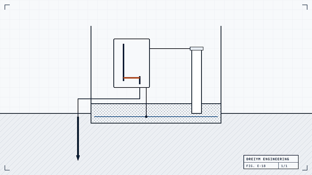
- Clear faults. When a hot conductor touches a metal enclosure, current flows on the EGC back to the service, through the main bonding jumper to the neutral, and back to the transformer. That low-impedance path lets enough current flow to trip the breaker quickly. The earth isn’t part of it: NEC 250.4(A)(5) says the earth shall not be considered an effective ground-fault current path. A light pole with its own ground rod but no EGC shows why. Even with a 25-ohm rod, a 120-volt fault pushes at most about 5 amps through the earth, too little to trip a 20-amp breaker, so the pole stays energized.
- Protect people. Bonding keeps metal surfaces at nearly the same voltage, so anyone touching two of them during a fault sees little difference, and fast clearing limits how long it lasts.
Why the Earth Is Not the Fault Path
NEC 250.4(A)(5) states that for grounded systems the earth shall not be considered an effective ground-fault current path. Soil resistance is far too high to let enough current flow to trip a breaker quickly, so a ground fault that returned only through the earth could leave metal parts energized. Fault current has to return to the source through the equipment grounding conductor, the bonding jumpers and the main bonding jumper. The grounding electrodes handle lightning, surges and keeping the system referenced to earth.
How Grounding Systems Are Tested
- Fall-of-potential test. Current is passed between the electrode and a remote current probe while a second probe measures voltage in between. For a single electrode in uniform soil, the reading with the potential probe at about 62 percent of the distance to the current probe is close to the true value. The electrode must be disconnected, or tested with the selective method using a current clamp, and large grids need very long leads. IEEE Std 81 is the usual guide; see our article on the fall-of-potential method.
- Clamp-on (stakeless) test. A clamp around the electrode conductor induces a voltage and measures the resulting current. It needs no probes but only works where the electrode is one of many in parallel, as on a utility’s multi-grounded neutral, and it measures the whole loop. It can’t test an isolated electrode, and a suspiciously low reading usually means it’s measuring a metal loop, not the earth.
- Continuity and bonding checks. Low-resistance ohmmeter readings between the main ground bar and each bonded item, such as water pipe, steel, telecom busbars and equipment frames, confirm the bonds are intact, along with a visual check of connections and of neutral-to-ground bonds.
Engineers also measure soil resistivity, usually with the Wenner four-pin method, before designing a ground ring or grid. Because resistance rises in dry or frozen soil, compare results taken in similar conditions. Our guides cover testing grounding electrodes and bonding systems and how often ground systems should be tested.
How Dreiym Engineering Can Help
Our grounding system tests measure how a facility’s grounding system performs against the NEC and the project specification. When an owner, utility, telecom carrier or data center requires an acceptance target below the NEC’s 25 ohms, we test to that target, and we test to ANSI/NETA ATS (acceptance) or MTS (maintenance) when specified. Our instruments include a Fluke® 1625-2 earth ground tester and a Radiodetection® PCMx, and reports are PE-stamped where required. Grounding tests are part of our electrical power engineering services, alongside short circuit analysis. Contact us for a free quote.